S300-DIN-RDR2S Module Hardware Installation
24-10239-413 Rev. A 3
This document contains confidential and proprietary information of Johnson Controls, Inc.
© 2010 Johnson Controls, Inc.
Package Contents
S300-DIN-RDR2S module
Cable for use with CK720/CK705 controllers, S300-RDR2 modules, or S300
input/output modules
This manual
Tools Needed
Small, straight-blade screwdriver for securing wires in the terminal blocks.
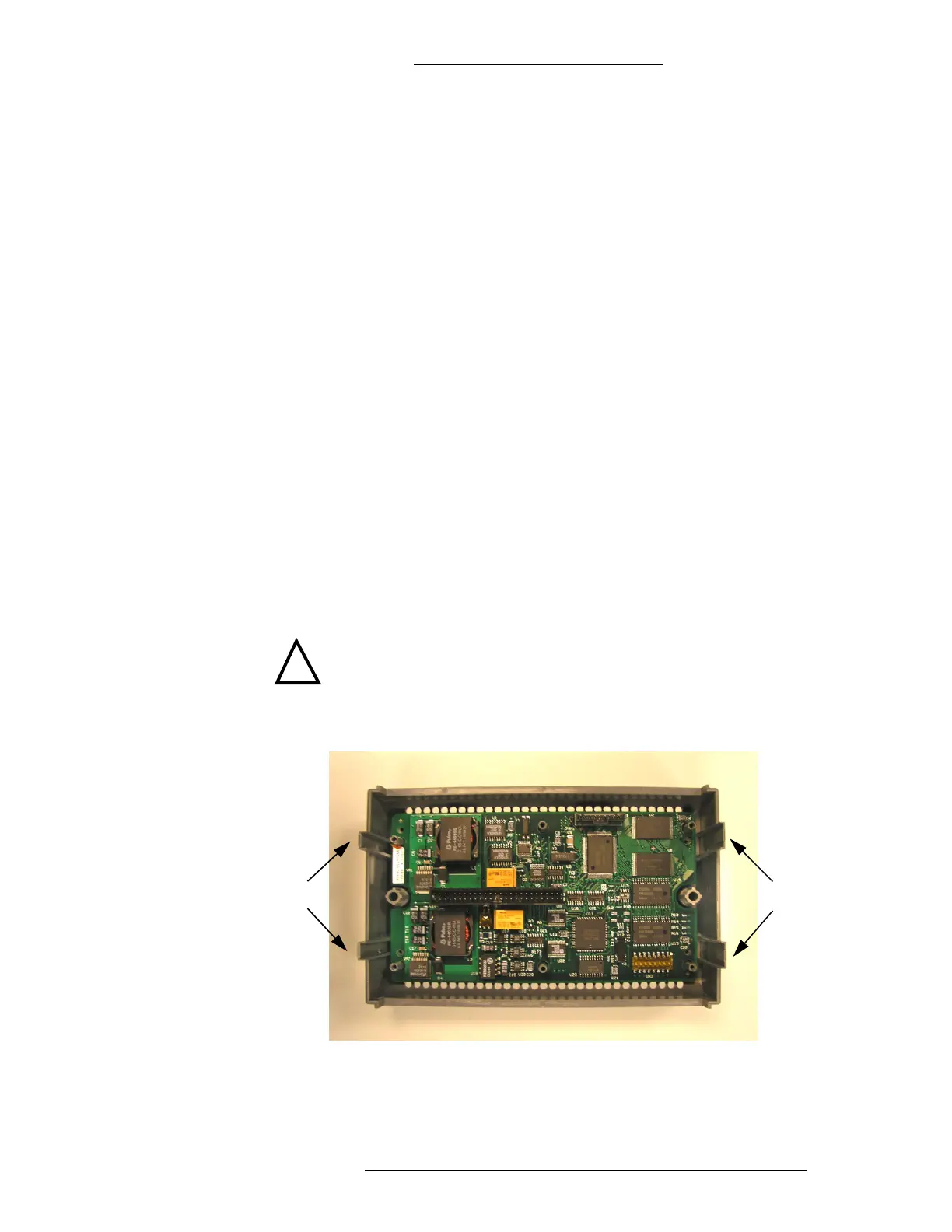
RDR2S Module Components
The RDR2S module consists of two electrical printed circuit boards (PCBs) in a
plastic enclosure. The bottom PCB is a wiring base and the top PCB is an electronics
board.
The electrical printed circuit boards are interconnected via a 2x25 pin header. The
bottom board (wiring base) is mounted onto
the bottom enclosure with four No 3
screws. The top board (electronics board) is mounted onto the top enclosure with
four No 3 screws. The separation between the two boards is approximately 1 inch.
The RDR2S module is shipped fully assembled.
!
CAUTION
If DC power has already been connected to the unit, disconnect the DC
power before separating the electronics board from the wiring base.
Guides
Guides
Electronics Board
 Loading...