System 450™ Series Control Modules with Relay Outputs Installation Instructions20
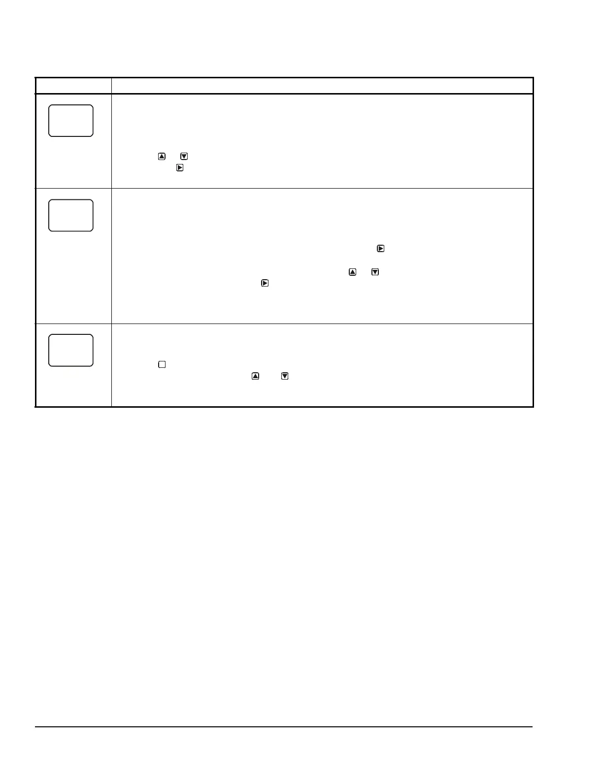
Sensor Failure Mode Selection Screen: Select the differential output’s mode of operation if either of the
referenced sensors (Sn-1 or Sn-2) or the sensor wiring fails. The output operates in the selected mode
until the failure is fixed. Sensor Failure Mode selections for Analog Outputs include:
• ON = Output generates the selected OEP signal strength during sensor failure.
• OFF = Output generates the selected OSP signal strength during sensor failure.
8. Press or to select this output’s mode of operation if a referenced sensor or sensor wiring
fail. Press
to save your selection and go to the Edit Sensor Selection screen.
The screen example shows OFF selected as the Sensor Failure mode for Output 2.
Edit Sensor Screen: This screen displays the Differential Sensor (Sn-d) that this output currently
references. Typically, no action is taken in this screen. But if you need to change the sensor that this
output references, you can select a different sensor for this output in this screen.
Note: If you change the Sn-d sensor to a different sensor, the output is no longer a Differential Control
output and you must set the output up again for the new sensor selection.
9. If you are not changing this output’s sensor, simply press to save the current sensor
selection and return to the Analog Output Setup Start screen.
To change the sensor this output references, press or to select the new sensor that this
output references. Then press to save the new sensor selection and return to the Setpoint
Selection screen (SP or dSP). If the new sensor has a different Sensor Type from the previously
referenced sensor, repeat the output setup procedure for this output.
The screen example shows Sn-d as the selected Sensor for Output 2.
Analog Output Setup Start Screen
After you have set up this Analog Output, you can go to another Output Setup Start screen, the Sensor
Setup Start screen, or return to the Main screens.
10. Press to scroll through the remaining Output Setup Start screens and return to the Sensor
Setup Start screen, or press and simultaneously to return to the System 450 Main
screens.
The screen example shows the Analog Output Setup Start screen for Output 2.
Table 11: System 450 Setup Screen Information and Procedures for Analog Outputs with Differential
Control (Part 3 of 3)
LCD Screen Name, Description/Function, User Action, Example
M
 Loading...