System 450™ Series Control Modules with Relay Outputs Installation Instructions10
Setting Up System 450 Outputs
After you build and connect power to your control
system module assembly, the output numbers and
output types for your control system are automatically
assigned in the UI.
Note: You must set up the input sensors for your
control system before you can set up the outputs. See
Setting Up System 450 Sensors
on page 7 for more
information.
To set up System 450 outputs in the UI:
1. Apply power to your module assembly. After the
Startup screen appears briefly (displaying the
control module firmware version), the Main screen
appears on the LCD.
2. In the Main screen, press and hold
and
simultaneously for 5 seconds to access the setup
screens and to go to the Sensor Setup Start
screen.
3. At the Sensor Setup Start screen, press
repeatedly to scroll through and select the desired
Output Setup Start screen. The Output Setup
Start screen indicates the output number and the
output type for the selected output.
4. To set up standard Relay Outputs and Relay
Outputs with High Input-Signal Selection, see
Setting
Up a Relay Output for Standard Control or
High Input-Signal Selection Control and Table 6 for
setup information and procedures.
5. For standard Analog Outputs and Analog Outputs
with High Input-Signal Selection, see S
etting Up an
Analog Output for Standard Control or High Input-
Signal Selection Control and Table 8 for setup
information and procedures.
6. For Relay Outputs with Differential Control, see
Setting
Up an Output for Differential Control on
page 16 and Table 10.
7. For Analog Outputs with Differential Control, see
Setting
Up an Output for Differential Control on
page 16 and Table 11.
Setting Up a Relay Output for Standard Control or
High Input-Signal Selection Control
Table 6 provides information, procedures, guidelines,
and screen examples for setting up relay outputs for
standard or High Input-Signal Selection control. See
Figure 7 on page 21 for example menu flow of the
Relay Output 1 set up in Table 6.
M
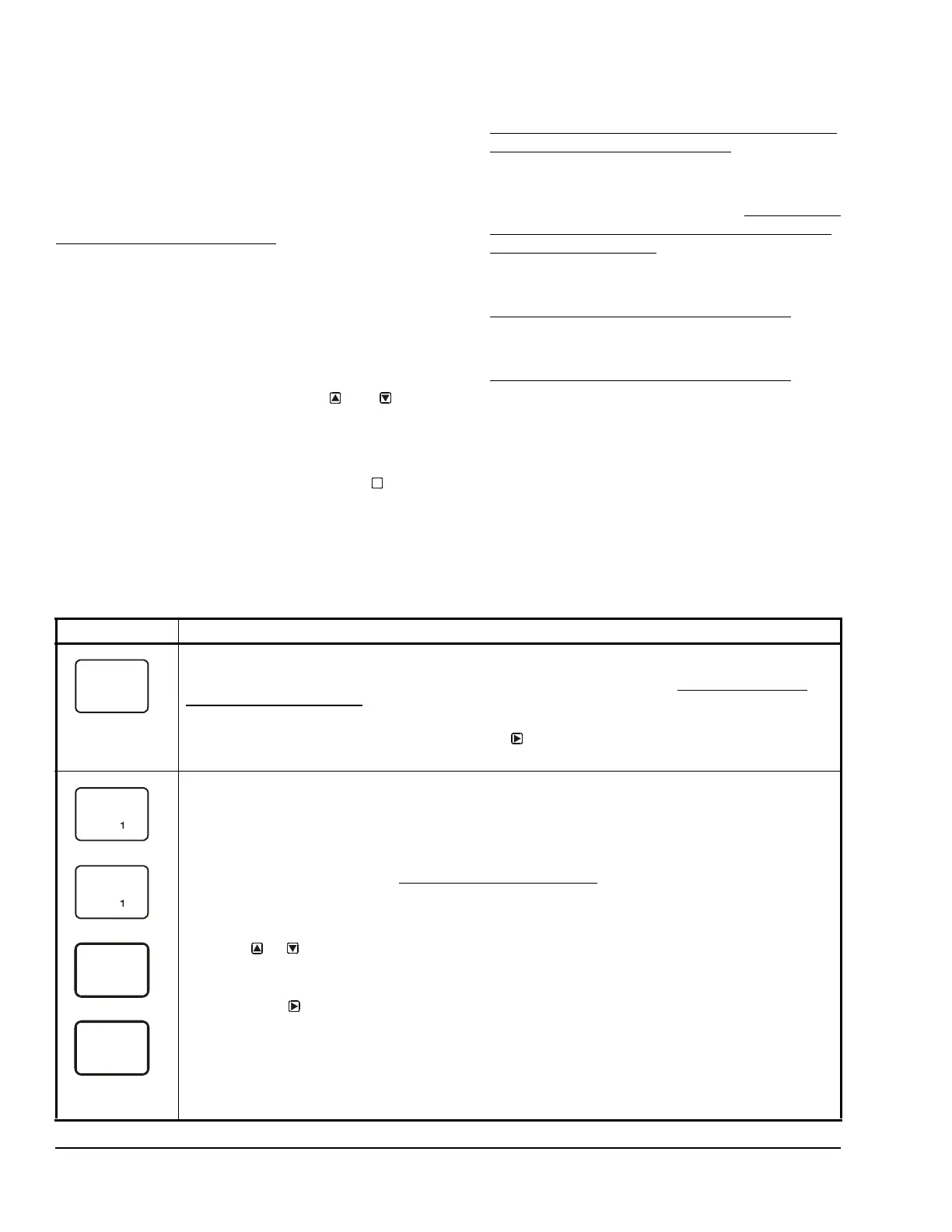
Table 6: System 450 Setup Screen Information and Procedures for Relay Outputs with Standard Control
and High Input-Signal Selection Control (Part 1 of 3)
LCD Screen Name, Description/Function, User Action, and Example
Relay Output Setup Start Screen: The output numbers and the output type (relay or analog) are
determined by the module types and configuration of your control system’s module assembly and are
automatically assigned when you connect power to the module assembly. (See Setting Up a Control
System in the User Interface on page 5.)
Note: You must set up the control system input sensors before you can set up the outputs.
1. In the Relay Output Setup Start screen, press
to go to the output’s Sensor Selection screen.
The screen example shows a Relay Output Setup Start screen for Output 1.
Sensor Selection Screen: The sensor you select here determines the output’s setup parameters and
values, including condition type, unit of measurement, minimum control band, default setup values, and
setup value ranges for several of the remaining output setup screens. If a sensor is not selected, the
remaining output setup screens do not appear. If a sensor is already selected for this output, the Sensor
Selection screen does not appear here and the Relay ON Selection (ON or dON) screen appears instead.
Note: You must select a sensor in this Sensor Selection screen and the selected sensor must be already
set up in the System 450 UI. (See Setting Up System 450 Sensors
.)
Note: Beginning with firmware Version 2.00, the functional sensors Sn-d and HI-2 are available, if Sn-1
and Sn-2 are the same Sensor Type. If Sn-1, Sn-2, and Sn-3 are the same Sensor Type, the functional
sensor HI-3 is also available.
2. Press or to select the sensor that this output references:
• For standard control action, select Sn-1, Sn-2, or Sn-3.
• For standard control action with High Input-Signal Selection, select HI-2 or HI-3.
Then press
to save your sensor selection and go to the Relay ON Selection screen.
Note: For Differential Control, select Sn-d and go to Table 10 on page 17 for information, procedures,
guidelines, and screen examples for setting up outputs for Differential Control.
The top screen example shows the initial Sensor Selection screen for Relay Output 1 before a sensor is
selected. The remaining screen examples show some of the sensors that may be available for selection.
For the Output Relay example, Sn-2 is selected as the Sensor for Output 1 as shown in the second
screen.
--
Sn-2

 Loading...


