System 450™ Series Control Modules with Relay Outputs Installation Instructions14
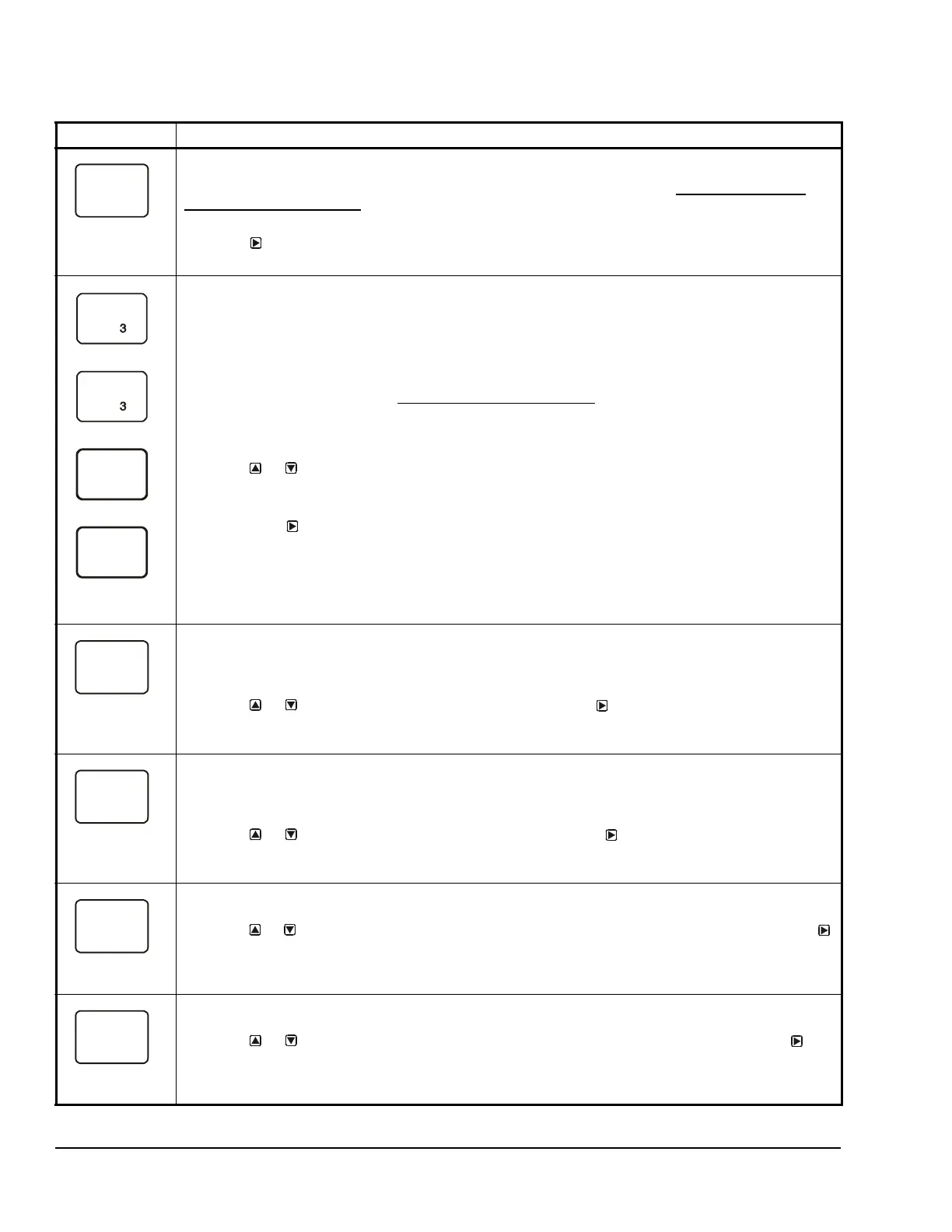
Table 8: System 450 Setup Screen Information and Procedures for Analog Output with Standard and High
Input-Signal Selection Control (Part 1 of 2)
LCD Screen Name, Description/Function, User Action, Example
Analog Output Setup Start Screen: The output numbers and the output type (relay or analog) are
determined by the module types and configuration of your control system’s module assembly and are
automatically assigned when you connect power to the module assembly. (See Setting Up a Control
System in the User Interface on page 5.)
Note: You must set up the system’s sensors before you can set up the outputs.
1. Press
to go to this output’s Sensor Selection screen.
The screen example shows the Analog Output Setup Start screen for Output 3.
Sensor Selection Screen: The sensor you select here determines this output’s setup parameters and
values, including condition type, unit of measurement, minimum proportional band, default setup values,
and setup value ranges for several of the remaining output setup screens. If a sensor is not selected here,
this output’s remaining setup screens do not appear. If a sensor is already selected for this output, the
Sensor Selection screen does not appear here, and the Setpoint Selection (SP or dSP) screen appears
instead.
Note: You must select a sensor in this Sensor Selection screen and the selected sensor must be already
set up in the System 450 UI. (See Setting Up System 450 Sensors
.)
Note: Beginning with firmware Version 2.00, the functional sensors Sn-d and HI-2 are available if Sn-1
and Sn-2 are the same Sensor Type. If Sn-1, Sn-2, and Sn-3 are the same Sensor Type, the functional
sensor HI-3 is also available.
2. Press or to select the sensor that this output references:
• For standard control action, select Sn-1, Sn-2, or Sn-3.
• For standard control action with High Input-Signal Selection, select HI-2 or HI-3.
Then press
to save your sensor selection and go to the Setpoint Selection screen.
Note: For Differential Control, select Sn-d and go to Table 11 on page 18 for information, procedures,
guidelines, and screen examples for setting up an Analog Output for Differential Control.
The top screen example shows the initial Sensor Selection screen for Analog Output 3 before a sensor is
selected. The remaining screen examples show some of the sensors that may be available for selection.
For the Analog Output example, Sn-1 is the selected Sensor for Output 3 as shown in the second screen.
Setpoint Selection Screen: Setpoint is the target value that the controlled system drives towards and
along with End Point, defines this output’s proportional band.
Note: An output’s minimum proportional band (between Setpoint and End Point) is automatically
enforced in the output’s Setpoint and End Point Selection screens.
3. Press or to select this output’s Setpoint value. Press
to save your Setpoint value
selection and go to the End Point Selection screen.
The screen example shows a SP value of 200 (psi) selected for Output 3.
End Point Selection Screen: End Point is the (condition) value that the controlled system drives away
from (towards Setpoint) and, along with Setpoint, defines this output’s proportional band.
Note: An output’s proportional band (between Setpoint and End Point) is automatically enforced in the
output’s Setpoint and End Point Selection screens.
4. Press or to select this output’s End Point value. Press
to save your End Point value
selection and go to the %Output Signal Strength at Setpoint Selection screen.
The screen example shows an EP value of 250 (psi) selected for Output 3.
Output Signal Strength at Setpoint Selection Screen: Select the strength of the signal that this output
generates when the sensed condition is at the Setpoint value. The signal strength range is 0 to 100 (%).
5. Press or to select this output’s %Output Signal Strength at Setpoint (OSP) value. Press
to save your selection and go to the %Output Signal Strength at End Point Selection screen.
The screen example shows an OSP value of 10 (%) selected for Output 3. Therefore Output 3 generates
10% of the total signal strength (1 V or 5.6 mA) when the input is at the Setpoint value of 200 (psi).
Output Signal Strength at End Point Selection Screen: Select the strength of the signal that this output
generates when the sensed condition is at the End Point value. The signal strength range is 0 to 100 (%).
6. Press or to select this output’s %Output Signal Strength at End Point value. Press
to
save your selection and go to the Integration Constant Selection screen.
The screen example shows an OEP value of 90 (%) selected for Output 3. Therefore Output 3 generates
90% of the total signal strength (9 V or 18.4 mA) when the input is at the End Point value of 250 (psi).
--
Sn-1

 Loading...


