System 450™ Series Control Modules with Relay Outputs Installation Instructions 7
Accessing the System 450 Setup Start Screens
Access the System 450 Setup Start screens from the
Main screen. See Table 2 for more information about
the Setup Start screens.
To access the System 450 setup screens:
1. Apply power to your module assembly. After the
Startup screen appears briefly (displaying the
control module firmware version), the Main screen
appears on the LCD.
2. In the Main screen, press and hold
and
simultaneously for 5 seconds to access the setup
screens and to go to the Sensor Setup Start
screen.
3. Press
repeatedly to scroll through the Output
Setup Start screens. See Figure 7.
Note: The UI returns to the Main screens after 2
minutes of inactivity in any screen in the UI.
Setting Up System 450 Sensors
You must set up the input sensors for your control
system before you can set up any of outputs. To set up
the input sensors you must access the setup screens.
See Accessing the System 450 Setup Start Screens
.
The Sensor Setup Start screen is the first screen
displayed when you access the system setup screens.
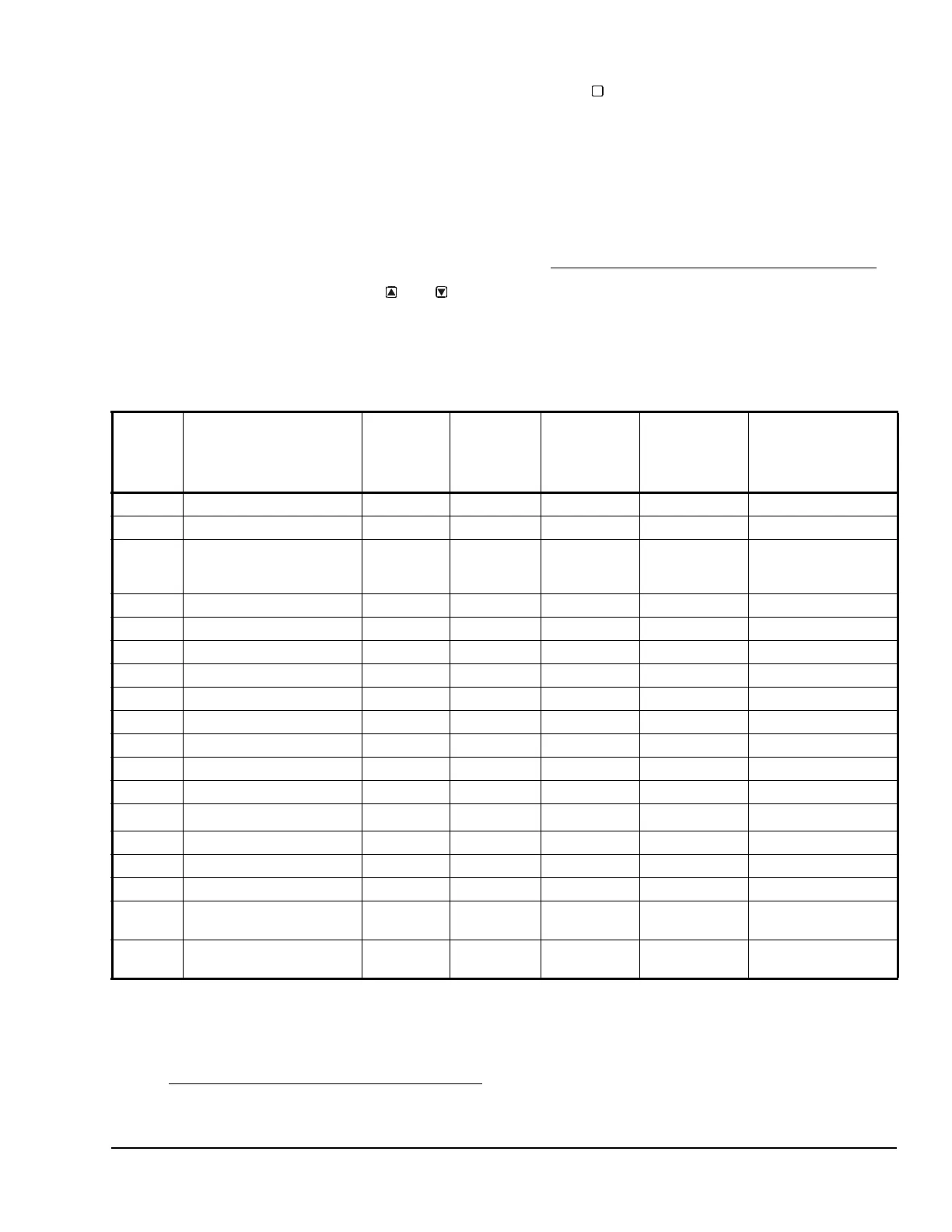
Table 3 provides information about System 450
sensors, Sensor Types, parameter values, and
specified sensor/transducer product code numbers.
M
Table 3: System 450 Sensor Types, Setup Values, and Sensor/Transducer Product Codes
Sensor
Type
Unit of Measurement
Value
(Condition/Units)
Effective
Sensing
Range
Range of
Usable
Values
1
Resolution
Increment
Value
Minimum
Proportional
or Control
Band
Sensor Product
Type Number
2
°F °F (Temperature/degrees) -46 to 255 -40 to 250 1 1 A99B-xxx
°C °C (Temperature/degrees) -43 to 124 -40 to 121 0.5 0.5 A99B-xxx
rH % (Humidity/%RH) 1 to 100 10 to 95 1 2 HE-67Sx-xxxxx
HE-67Nx-xxxxx
HE-68Nx-0N00WS
P 0.5 INWC (Pressure/in. W.C.) 0 to 0.5 0.025 to 0.5 0.005 0.025 DPT2650-0R5D-AB
P 2.5 INWC (Pressure/in. W.C.) 0 to 2.5 0.1 to 2.5 0.02 0.1 DPT2650-2R5D-AB
P 5 INWC (Pressure/in. W.C.) 0 to 5.0 0.25 to 5.0 0.05 0.25 DPT2650-005D-AB
P 8 bAR (Pressure/bar) -1 to 8 -1 to 8 0.05 0.1 P499Rxx-401C
P 10 INWC (Pressure/in. W.C.) 0 to 10 0.5 to 10 0.05 0.2 DPT2650-10D-AB
P 15 bAR (Pressure/bar) -1 to 15 -1 to 15 0.1 0.2 P499Rxx-402C
P 30 bAR (Pressure/bar) 0 to 30 0 to 30 0.1 0.4 P499Rxx-404C
P 50 bAR (Pressure/bar) 0 to 50 0 to 50 0.2 0.4 P499Rxx-405C
P100 PSI (Pressure/psi) 0 to 100 0 to 100 0.5 1 P499Rxx-101C
P110
3
Hg/PSI (Pressure/Hg-psi) -10 to 100 -10 to 100 0.5 1 P499Rxx-100C
P200 PSI (Pressure/psi) 0 to 200 0 to 200 1 1 P499Rxx-102C
P500 PSI (Pressure/psi) 0 to 500 90 to 500 1 5 P499Rxx-105C
P750 PSI (Pressure/psi) 0 to 750 150 to 750 2 6 P499Rxx-107C
HI°F °F (Temperature/degrees) -50 to 340
-40 to 340
4
1 1 TE-631x, TE-6000-x
TE-68NT-0N00S
HI°C °C (Temperature/degrees) -45.5 to
170
-40 to 170
4
0.5 0.5 TE-631x, TE-6000-x
TE-68NT-0N00S
1. Because of the way that the System 450 Differential Sensor (Sn-d) is set up and calculated with two identical sensors (Sn-
1 and Sn-2), the Range of Usable Values is twice as large as a single sensor. Each Sensor Type has an equal number of
positive and negative values. See Table 9 for the Range of Usable Values when an output references Sn-d.
2. Refer to the System 450 Series Modular Controls Product Bulletin (LIT-12011458), Catalog Page (LIT-1900549), or
Technical Bulletin (LIT-12011459) for additional ordering information for System 450 compatible sensors and transducers.
3. See Setting Up Outputs
That Reference a P110 Sensor on page 9 for information on setting up System 450 outputs that
reference the P110 Sensor Type.

 Loading...


