System 450™ Series Control Modules with Relay Outputs Installation Instructions 9
Setting Up Outputs That Reference a P110 Sensor
The P110 Sensor Type can monitor negative pressure
down to 20 InHg (-10 psi). When referencing a P110
sensor, System 450 displays negative pressure values
in InHg on the Main and System Status screens.
But when you set up an output that references a P110
sensor and the setup value is a negative pressure
value, you must select a pressure value in negative psi.
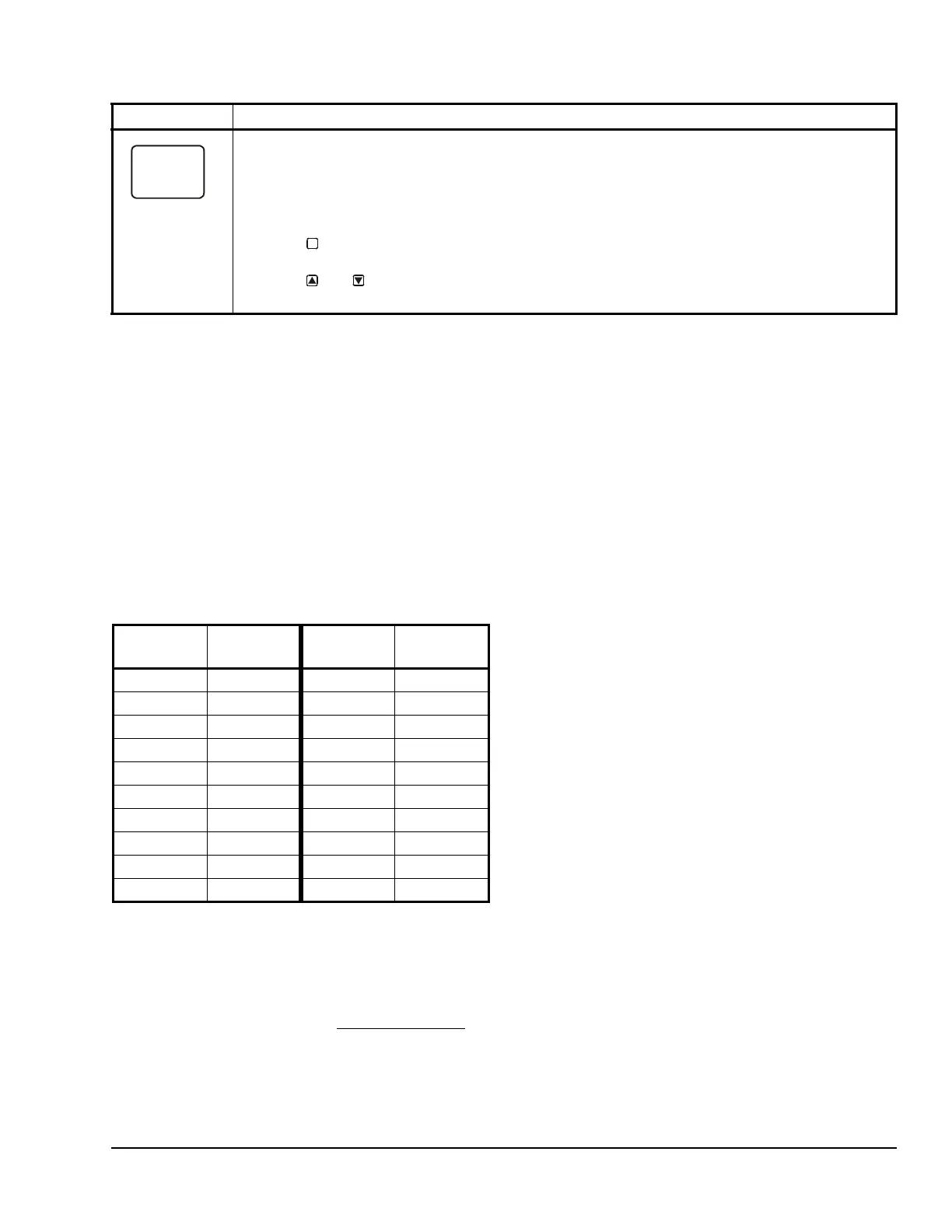
Use Table 5 to determine the negative PSI setup value
that corresponds to your InHg target value. For
example, if you want a relay output to go off when the
sensed pressure reaches 7 InHg, you select the value
-3.5 (psi) in the output’s Relay OFF Selection screen.
Note: When an output references the P110 Sensor
Type and the output is set up for Differential Control
(Sn-1 and Sn-2 are P110 Sensor Type), the negative
pressure values displayed in the differential pressure
System Status screen (dIFP) are displayed as negative
psi values, not InHg values. See Differential Control
on
page 16 for more information.
High Input-Signal Selection
Beginning with firmware Version 2.00, standard System
450 control modules include the High Input-Signal
Selection control capability.
The High Input-Signal Selection feature enables a
System 450 control system to monitor a condition
(temperature, pressure, or humidity) with two or three
sensors (of the same type) and control relay and/or
analog outputs based on the highest condition value
sensed by the two or three referenced sensors.
In two sensor applications (HI-2), Sn-1 and Sn-2 must
be the same Sensor Type. In three sensor applications
(HI-3), Sn-1, Sn-2, and Sn-3 must be the same Sensor
Type.
A System 450 control system, using High Input-Signal
Selection, can monitor the outlet pressures of two
condenser coils in a multi-circuit condensing unit using
two pressure sensors of the same type; one connected
to each coil outlet.
If the multi-circuit condensing unit has single speed fan
motors, multiple relay outputs can be set up to
reference the high input-signal and System 450 can
stage the fans on and off based on the pressure
sensed at the coil with the highest pressure.
If the multi-circuit condensing unit has variable speed
fan motors, one or more analog outputs can be set up
to reference the high input-signal and control the fan
motor speeds based on the pressure sensed at the coil
with the highest pressure.
Sensor Setup Start Screen: When you have finished setting up all of the sensors for your control
system, the display returns to the Sensor Setup Start screen.
Note: You can edit the sensor set up values at any time, if required. However, changing the Sensor Type
for a sensor that is referenced by an output requires setting up the output again to the new Sensor Type
values.
After the sensors are set up for your control system, you can:
• Press to scroll through the Output Setup Start screens and begin setting up your system
outputs.
• Press and simultaneously to return to the Main screens.
The screen example shows Sensors Setup Start screen with flashing dashes.
Table 4: System 450 Sensor Setup Screen Information and Procedures (Part 2 of 2)
LCD Screen Name, Description/Function, User Action, and Example
M
Table 5: InHg Target Values/PSI Setup Values
InHg
Value
psi Setup
Value
InHg
Value
psi Setup
Value
1 -0.5 11 -5.5
2 -1.0 12 -6.0
3 -1.5 13 -6.5
4 -2.0 14 -7.0
5 -2.5 15 -7.5
6 -3.0 16 -8.0
7 -3.5 17 -8.5
8 -4.0 18 -9.0
9 -4.5 19 -9.5
10 -5.0 20 -10.0

 Loading...


