System 450™ Series Control Modules with Relay Outputs Installation Instructions 11
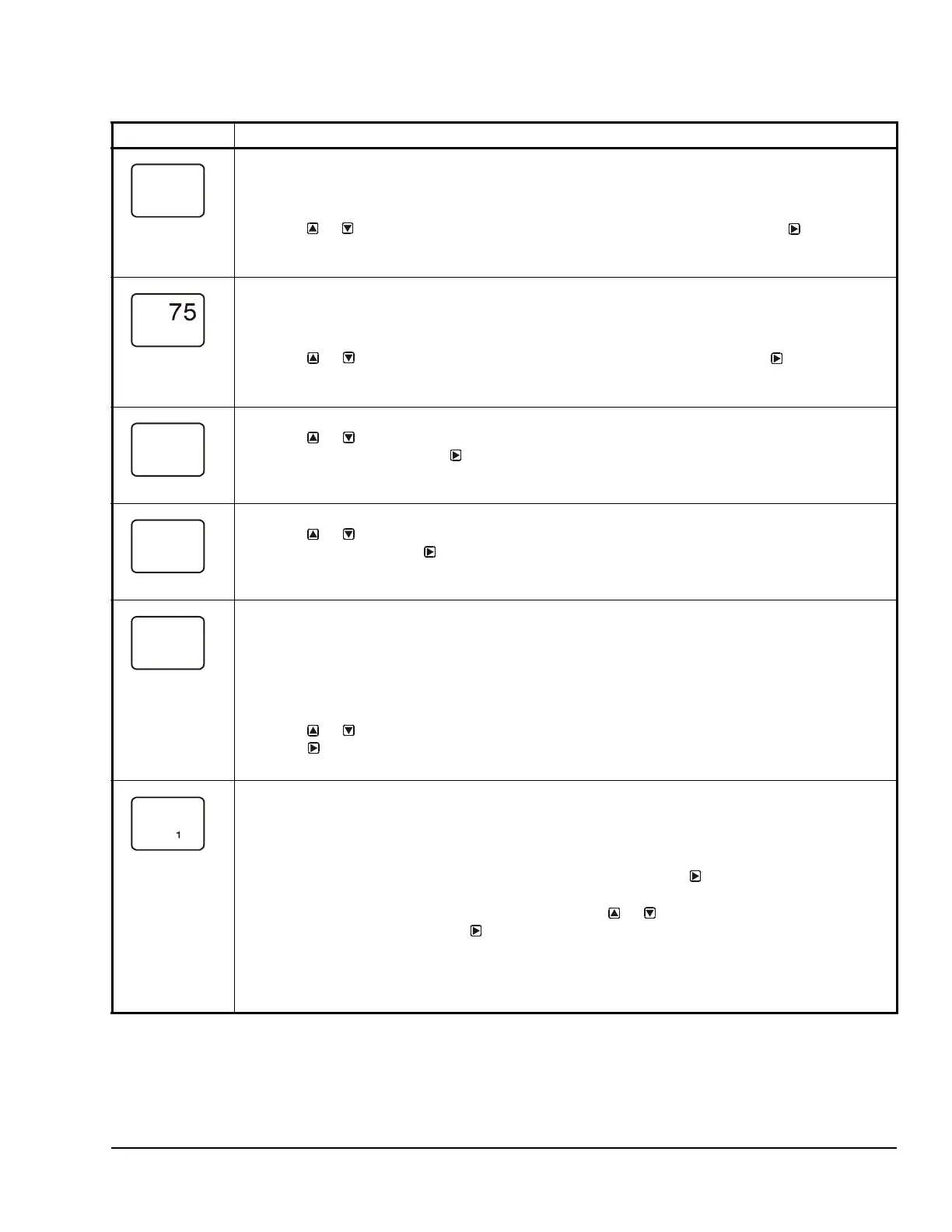
Relay ON Selection Screen: Select the value at which the relay turns On. Relay ON is defined as relay
LED On/Lit, relay contacts N.O. to C are closed, and N.C. to C contacts are open.
Note: The value ranges and minimum control band are determined by the Sensor Type selected for the
sensor that the output references and are enforced in the Relay ON and Relay OFF Selection screens.
3. Press or to select the value at which the output relay turns On, then press
to save your
selection and go to Relay OFF Selection screen.
The screen example shows an ON value of 78 (°F) selected for Relay Output 1.
Relay OFF Selection Screen: Select the value at which the relay turns Off. Relay OFF is defined as
relay LED Off, relay contacts N.C. to C are closed, and N.O. to C contacts are open.
Note: The value ranges and minimum control band are determined by the Sensor Type selected for the
sensor that the output references and are enforced in the Relay ON and Relay OFF Selection screens.
4. Press or to select the value at which output relay turns Off, then press
to save your
selection and go to Minimum Relay ON TIme Selection screen.
The screen example shows an OFF value of 75 (°F) selected for Relay Output 1.
Minimum Relay ON Time Selection Screen: Minimum ON Time range is 0 to 300 seconds.
5. Press or to select the minimum time that the output relay remains On after reaching the
Relay ON value, then press
to save your selection and go to the Minimum Relay OFF Time
Selection screen.
Screen example shows an ONT value of 0 (seconds) selected for Output 1.
Minimum Relay OFF Time Selection Screen: Minimum OFF Time range is 0 to 300 seconds.
6. Press or to select the minimum time that this output relay remains Off after reaching the
Relay OFF value. Press
to save your selection and go to the Sensor Failure Mode Selection
screen.
The screen example shows an OFFT value of 120 (seconds) selected for Output 1.
Sensor Failure Mode Selection Screen: Select the output’s mode of operation if a referenced sensor or
sensor wiring fails. If the output references functional sensors HI-2 or HI-3, the output enters the Sensor
Failure mode whenever a referenced sensor or sensor wiring fails. The output operates in the selected
Sensor Failure mode until the failure is remedied. Sensor Failure mode selections for Relay Outputs
include:
• ON = Output relay remains On during sensor failure.
• OFF = Output relay remains Off during sensor failure.
7. Press or to select this output’s mode of operation if the sensor or sensor wiring fails.
Press
to save your sensor failure mode selection and go to the Edit Sensor screen.
The screen example shows OFF selected as the Sensor Failure mode for Output 1.
Edit Sensor Screen: This screen displays the sensor that this output currently references. Typically, no
action is taken in this screen. But if you need to change the sensor that this output references, you can
select a different sensor for this output in this screen.
Note: If you change the sensor that an output references to a sensor with a different Sensor Type, the
default setup values for the output change, and you must set the output up again.
8. If you do not need to change this output’s sensor, simply press to save the current sensor
selection and return to the Relay Output Setup Start screen.
To change the sensor this output references, press or to select the new sensor that this
output references. Then press to save the new sensor selection and return to the Relay ON
Selection screen (ON or dON). If the new sensor has a different Sensor Type from the
previously referenced sensor, repeat the output setup procedure for this output.
This Relay Output is now set up in the System 450 UI.
The screen example shows Sn-2 is selected Sensor for Output 1.
Table 6: System 450 Setup Screen Information and Procedures for Relay Outputs with Standard Control
and High Input-Signal Selection Control (Part 2 of 3)
LCD Screen Name, Description/Function, User Action, and Example
Sn-2

 Loading...


