System 450™ Series Control Modules with Relay Outputs Installation Instructions12
Setting Up an Analog Output for Standard Control
or High Input-Signal Selection Control
Analog outputs provide an analog signal to control
equipment in you application based on the input from a
standard fixed setpoint sensor (Sn-1, Sn-2, or Sn-3) or
a High Input Signal Selection sensor (HI-2 or HI-3).
Note: The differential sensor, Sn-d, is used to set up
analog and relay outputs for Differential Control. See
Setting
Up an Output for Differential Control on page
16 for more information.
Analog outputs provide an auto-selecting analog signal
that is proportional to the sensed input condition. The
System 450 analog output senses the impedance of
the controlled equipment’s analog input circuit and
automatically delivers either a 0–10 VDC or 4–20 mA
signal to the controlled equipment.
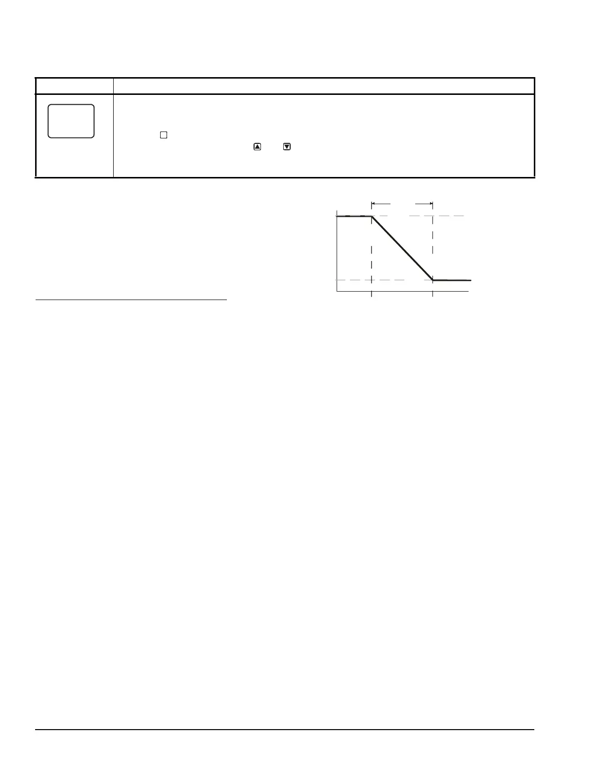
Figure 6 shows an example of the analog output setup
values and the resulting output signal in a typical space
heating application (SP > EP and OSP < OEP).
The control action between the input signal and the
output signal can be set up four ways, depending on
the values selected for the Setpoint (SP), End Point
(EP), Percent Output Signal Strength at Setpoint
(OSP), and Percent Output Signal Strength at End
Point (OEP). The LCD displays different Control Ramp
icons for the four control actions.
Relay Output Setup Start Screen
After you have set up this Relay Output, you can go to another Output Setup Start screen, the Sensor
Setup Start screen, or return to the Main screens.
9. Press to scroll through the remaining Output Setup Start screens and return to the Sensor
Setup Start screen, or press and simultaneously to return to the System 450 Main
screens.
The screen example shows a Relay Output Setup Start screen for Output 1.
Table 6: System 450 Setup Screen Information and Procedures for Relay Outputs with Standard Control
and High Input-Signal Selection Control (Part 3 of 3)
LCD Screen Name, Description/Function, User Action, and Example
M
System Output
Condition Value
Less Greater
65°F
10%
70°F
SP > EP
SP = 70 ( )
EP = 65 ( )
OSP = 10 (%)
OEP = 100 (%)
OSP
SP
EP
Proportional
Band
Fig:sys450_cntrl_rmp_exmpl
Figure 6: Control Ramp Example for a Typical
Heating Application (SP > EP and OSP < OEP)

 Loading...


