System 450™ Series Control Modules with Relay Outputs Installation Instructions22
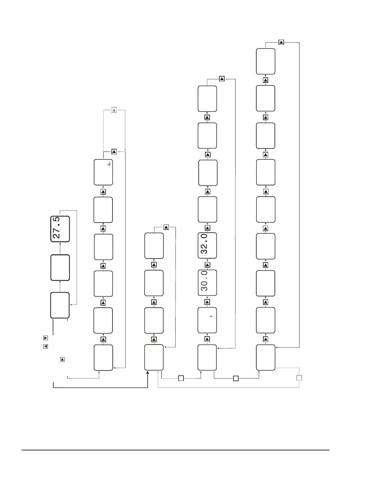
Figure 8: System 450 Status Screens, Setup Screens, and Menu Flow Example for Differential Control
Relay Output
Setup Start
OUTR
1
-- -
Up to
ten
Outputs
can be
connected
and
set up.
M
Relay
Output
1
OUTA
2
OutputAnalog
Setup Start
Analog
Output
2
Select Relay ON
Differential Value
dON
1
dOFF
1
Select Relay OFF
Differential Value
Select Minim
um
ime
Select Sensor
Failure Mode
SNF
1
OFF
Select Minimum
Relay OFF Time
OFFT
1
30
Select
Setpoint Value
Differential
dSP
2
30.0
Sele
ct Differential
Point Value
dEP
2
5.0
Select Integration
Constant Value
I-C
2
0
Select % Output
Signal Value
at Setpoint
OSP
2
0
Select % Output
Signal Value
at End Point
OEP
2
100
Select Sensor
Failure Mode
SNF
2
OFF
FIG:Sys450_diffcontrol_menu_flow_chart
M
Main Screen
Sensor 2 Status
Main Screen
Sensor 1 Status
Relay Output 1
Status
OUT
1
Analog Output 3
Status
50
OUT
2
Sensor 3 Status
----
3
Sensor 2 Status Sensor 1 Status
Sensor Setup
Screens
System Status
Screens
Main Screens
(Sensor Status)
Relay Output
Setup Screens
for Differential
Control
Analog Output
Setup Screens
for Differential
Control
M
Press and hold +
for 5 seconds to go to
the Setup Start screens.
Press to scroll through
Sensor Status screens and
Output Status screens.
Select
Control Sensor
Sn-d
SENS
SENS
Sensor Type
Setup Start
-- -
Select Sensor 2
Type
P100
Select Sensor 3
Type
Select Sensor 1
Type
--
Sn-1
Sn-2 Sn-3
SENS
2
Edit
Control Sensor
Sn-d
Select
Control Sensor
SENS
2
Sn-d
Edit
Control Sensor
SENS
1
Sn-d
On
-- -
P100
62.5
1
PSI
35.0
PSI
2
62.5
PSI
1
35.0
PSI
2
Selections for Setting Up Relay Output 1 to Enable/Disable Variable Speed Drive for Booster Pump by Pressure Differen
tial
(Drive On when Sn-d reports a 28 psi or less differential and drive Off when Sn-d reports a 30 psi or greater differential.)
(No Sensor)
Selections for Setting Up Analog Output 2 to Control Variable Speed Drive for Booster Pump by Pressure Dif
ferential
(Drive delivers 5% output at 25 psi or greater differential and ramps up 100% outp
ut at 20 psi or less.)
as pressure differential decreases, delivering
Because the same Sesnor Type (P100) is selected for Sn-1 and
Sn-2,
the Differential Control sensor (Sn-d) is available for selection wh
en the
outputs for this control system are set up.
The High Input-Signal Selection sensor for two sensor app
lications
(HI-2) is also available for selection when Sn-1 and Sn-2 are the
same
Sensor Type.
Note:
DIfP
Differential Control
Sensor Status
DIfP
Differential Control
Sensor Status
Main Screens show status of Sn-1, Sn-2, and Sn-d.
(Sn-d is Status screen is labeled DIfP (Differential
Pressure) because Sn-1 and Sn-2 are the same
pressure Sensor Type (P100).
Up to ten Ou
tputs
and
.
27.5
Note:
For more information on setting up Relay Output 1 and Analog Output 2 see Table 10 and Table
11.

 Loading...


