2 T-5800-3/T-5800-4 Technical Bulletin
Cover Removal
The cover can be removed by
applying an inward pressure to
one of the black tabs of the
receiver-controller main body to
unlatch it. The cover can also
be removed by simply taking
hold of the top and bottom sides
of the cover and pulling outward.
Oil Indicating Supply Air Filter
Check the oil indicating supply
air filter and replace as
necessary (A-4000-137 ordered
separately). When the filter is
dirty, a pressure drop will occur.
When filtering oil-contaminated
air, the filter will change from
white to red in color. If frequent
changes are necessary, check
the air supply system to
determine the cause of dirty or
oil-contaminated air.
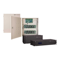
Positioning the Action and
Orifice Jumpers
The T-5800 must be
programmed according to the
system requirements. Both dual
input receiver-controllers are
factory set in the direct acting
mode with reverse readjustment.
The action and readjustment can
be changed by interchanging the
placement of the tube ends from
one lower spigot to the other
lower spigot (see Figs. 4, 11,
and 15).
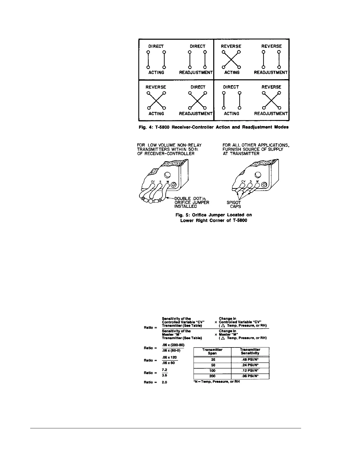
Each dual input T-5800 is
furnished with a double .007 in.
orifice jumper and three yellow
spigot caps (see Fig. 5). The
orifice jumper provides a
restricted source of supply to low
volume non-relay type
transmitters. For best results, it
is recommended that this jumper
be used when the low volume
transmitter is located within 50 ft.
(15m) of the receiver-controller.
For all other applications, it is
recommended that the spigots
be capped and a source of
supply be furnished at the
transmitter.
Precalibration Setup
Using the graph on Form 561,
prepare a readjustment
schedule (similar to the example
in Fig. 6) with respect to job
requirements, action, range of
readjustment, transmitter spans,
and pressures. Use the graph
and transmitter span vs. output
comparison chart
to illustrate the pressure
relationship of master “M” input
vs. controlled variable “CV”
input. Locate the two end points
of the control schedule and
connect with a straight line.
The receiver-controller ratio is
determined by the following
formula:
 Loading...