TEC26x7-4 Series BACnet® MS/TP Networked Thermostat Controllers with Two
Outputs Installation Instructions
Applications
The TEC26x7-4 Series Thermostat Controllers are
BACnet® Master-Slave/Token-Passing (MS/TP)
networked devices that provide control of local
hydronic reheat valves, pressure dependent Variable
Air Volume (VAV) equipment with or without local
reheat, or other zoning equipment using an on/off,
floating, or proportional 0 to 10 VDC control input. The
technologically advanced TEC26x7-4 Series
Thermostat Controllers feature a Building Automation
System (BAS) BACnet MS/TP communication
capability that enables remote monitoring and
programming for efficient space temperature control.
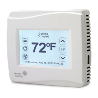
The TEC26x7-4 Series Thermostat Controllers feature
an intuitive user interface with backlit display that
makes setup and operation quick and easy. The
thermostat controllers also employ a unique,
Proportional-Integral (PI) time-proportioning algorithm
that virtually eliminates temperature offset associated
with traditional, differential-based thermostat
controllers.
North American Emissions Compliance
United States
Canada
Installation
Location Considerations
Locate the TEC26x7-4 Series Thermostat Controller:
• on a partitioning wall, approximately 5 ft (1.5 m)
above the floor in a location of average
temperature
• away from direct sunlight, radiant heat, outside
walls, behind doors, air discharge grills, stairwells,
or outside doors
• away from steam or water pipes, warm air stacks,
unconditioned areas (not heated or cooled), or
sources of electrical interference
Note: Allow for vertical air circulation to the
TEC26x7-4 Series Thermostat Controller.
IMPORTANT: The TEC26x7-4 Series Thermostat
Controllers are intended to provide an input to
equipment under normal operating conditions.
Where failure or malfunction of the thermostat
controller could lead to personal injury or property
damage to the controlled equipment or other
property, additional precautions must be designed
into the control system. Incorporate and maintain
other devices, such as supervisory or alarm systems
or safety or limit controls, intended to warn of or
protect against failure or malfunction of the
thermostat controller.
This equipment has been tested and found to
comply with the limits for a Class A digital device
pursuant to Part 15 of the FCC Rules. These limits
are designed to provide reasonable protection
against harmful interference when this equipment is
operated in a commercial environment. This
equipment generates, uses, and can radiate radio
frequency energy and, if not installed and used in
accordance with the instruction manual, may cause
harmful interference to radio communications.
Operation of this equipment in a residential area is
likely to cause harmful interference, in which case
the user will be required to correct the interference
at his/her own expense.
This Class (A) digital apparatus meets all the
requirements of the Canadian Interference-Causing
Equipment Regulations.
Cet appareil numérique de la Classe (A) respecte
toutes les exigences du Règlement sur le matériel
brouilleur du Canada.