TEC26x7-4 Series BACnet® MS/TP Networked Thermostat Controllers with Two Outputs Installation
Instructions
To install the thermostat controller:
1. Use a Phillips-head screwdriver to remove the
security screw if it is installed on the bottom of the
thermostat controller cover.
Note: Normally, the security screw is packaged
separately in a plastic bag with the thermostat
controller. Skip this step if the screw is not installed
on the bottom of the cover.
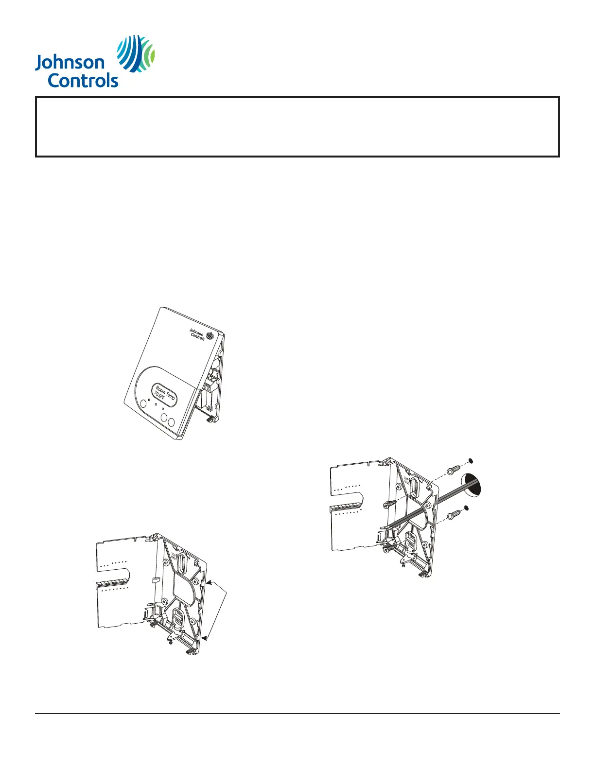
2. Pull the bottom edge of the thermostat controller
cover and open the thermostat controller as
illustrated in Figure 1.
3. Carefully pull the locking tabs on the right side of
the thermostat controller mounting base and
unlock the Printed Circuit Board (PCB). Open the
PCB to the left as illustrated in Figure 2.
4. Pull approximately 6 in. (152 mm) of wire from the
wall and insert the wire through the hole in the
thermostat controller mounting base.
5. Align the thermostat controller mounting base on
the wall and use the base as a template to mark
the two mounting hole locations.
6. Position the thermostat mounting base so that the
arrow on the base points upward to indicate the top
of the thermostat.
Note: If you need to install the thermostat on an
electrical junction box, use 2-1/2 x 4 in.
(63 x 101 mm) square boxes with mud ring covers,
and avoid smaller 1-1/2 x 4 in. (38 x 101 mm)
square or 3 x 2 in. (76 x 51 mm) boxes. This
procedure ensures you have enough space for
cabling and end-of-line devices, if needed.
Note: For surface-mount applications, use
durable mounting hardware such as Molly bolt
anchors that cannot be easily pulled out of the
mounting surface.
7. Secure the base to the wall surface using two
mounting screws as illustrated in Figure 3.
Note: Be careful not to overtighten the mounting
screws.
8. Swing the PCB back to the right and carefully snap
it into the locking tabs on the thermostat controller
mounting base.
9. Remove the screw terminal blocks that are
attached to a disposable adhesive. Figure 4
illustrates the locations of the screw terminal
blocks on the thermostat controller.