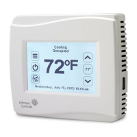
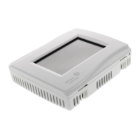
TEC26x7-4 Series BACnet® MS/TP Networked Thermostat Controllers with Two Outputs Installation
Instructions
Connecting the MS/TP Bus
To connect the MS/TP Bus:
1. Set the MS/TP address of the TEC BACnet MS/TP
Network Series Thermostat Controller per the
engineering drawings and test for bus voltage,
polarity, and isolation prior to wiring the MS/TP
Bus. Use the Com addr parameter to set the
MS/TP address for the thermostat controller.
Note: The wiring rules for the MS/TP Bus differ
from the wiring rules for the N2 Bus. For more
details on wiring the MS/TP Communications Bus,
refer to the MS/TP Communications Bus Technical
Bulletin (LIT-12011034).
2. Observe the polarity when connecting the bus
wires to the thermostat controller.
3. After the bus wires are connected to the first
thermostat controller, continue in a daisy-chained
fashion to the next thermostat controller.
Note: The bus wiring must be twisted-pair lines.
Do not run the bus wiring in the same conduit as
line voltage wiring (30 VAC or above) or other
wiring that switches power to highly inductive loads
(such as contactors, coils, motors, or generators).
The MS/TP Bus requires proper termination and
biasing at each end of a segment (a segment is a
physically continuous length of wire). Because the
rooftop controller is not equipped with end-of-line
termination, a Johnson Controls MS-BACEOL-0
End-of-Line Terminator (see Table 5; ordered
separately) or similar device is recommended to
provide this end-of-line termination. An end-of-line
terminator is required if a supervisory controller is not
at the end of the segment. If a supervisory controller is
at the end of the segment, then the end-of-line
terminator switch on the supervisory controller must be
set in the ON position.
The thermostat controller has automatic baud rate
detection. Do not exceed the maximum number of
devices allowed on a field bus. Be sure that the wiring
terminations are set correctly and that all
communication wiring is daisy-chained with no taps.
A small green light under the thermostat controller
cover (on the left edge when facing the thermostat
controller) indicates the communications mode when
the thermostat controller is operating.
The following blink codes may be seen:
• Short-Short-Long: Indicates that the baud rate is
known and that communication is active.
• Short-Short: Indicates that the thermostat
controller is scanning for the correct baud rate and
that there is no communication.
• Off: Indicates that there is no power to the
thermostat controller or that the MS/TP wiring
polarity is reversed.
• Long: Indicates that the MS/TP communication
daughter board is the wrong type for the main
board.
MS/TP Thermostat Controller Mapping
For detailed information on MS/TP Bus objects and
thermostat controller mapping, refer to the TEC
BACnet MS/TP Network Series Thermostat Controllers
Technical Bulletin (LIT-12011592).
 Loading...


