TEC3000 Series On/Off or Floating Fan Coil and Zoning Thermostat Controllers with Dehumidification
Capability Installation Instructions
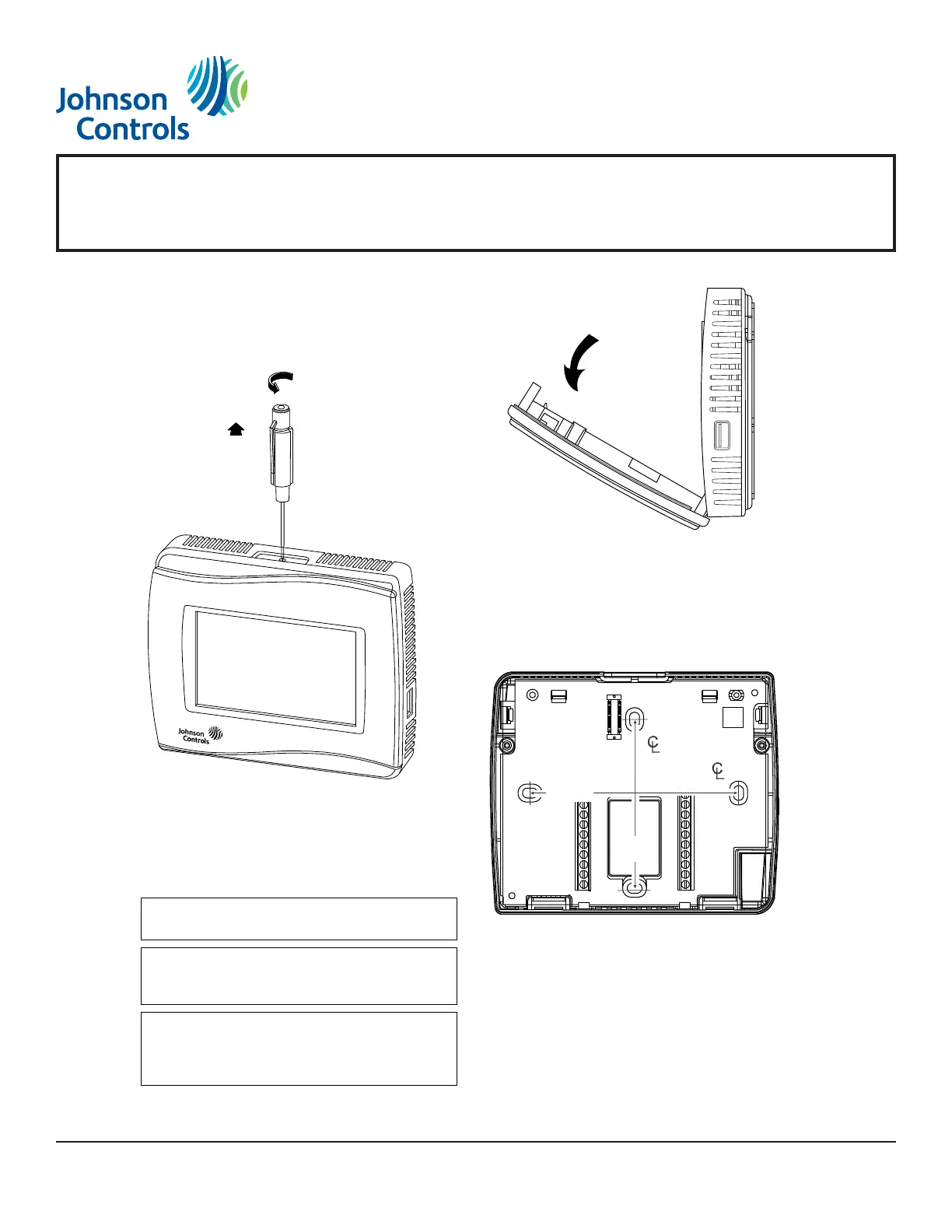
Installing the Thermostat Controller
1. Use a 1/16 in. (1.5 mm) Allen wrench or
Johnson Controls® T-4000-119 Allen-Head
Adjustment Tool (order separately) to remove the
security screw if it is installed on the top of the
thermostat controller cover.
2. Pull the top edge of the cover and open the
thermostat controller as illustrated in Figure 3.
3. Align the thermostat controller mounting base on
the wall with the security screw on the top, and use
the base as a template to mark the two mounting
hole locations.
Note: If you need to install the thermostat
controller on an electrical junction box, use
2-1/2 x 4 in. (63 x 101 mm) square boxes with mud
ring covers, and avoid smaller 1-1/2 x 4 in.
(38 x 101 mm) square or 3 x 2 in. (76 x 51 mm)
boxes. This procedure ensures that you have
enough space for cabling if needed.
IMPORTANT: The cover is not secured on the
bottom. Be careful not to drop the cover.
IMPORTANT: If you are installing more than one
thermostat controller, keep track of which cover
attaches to which base.
IMPORTANT: Use proper electrostatic discharge
(ESD) precautions during installation and servicing
to avoid damage to the electronic circuits of the
thermostat controller.