TFP1581
Page 11 of 14
of any other authorities having juris-
diction. Contact the installing contrac-
tor or product manufacturer with any
questions.
Automatic sprinkler systems are rec-
ommended to be inspected, tested,
and maintained by a qualified Inspec-
tion Service in accordance with local
requirements and/or national code.
The Model PRV-1
A Pressure Reducing
Valve requires no lubrication, packing
or preventative maintenance; however,
replacement of the diaphragm every
five years is recommended.
Flow Tests
Flow tests per NFPA are required every
five years, at which point the outlet
pressure is compared to previous
tests. If necessary the Model PRV-1
A
Valve can be readjusted following the
Placing the Valve in Service section.
If the desired pressure cannot be
achieved, the Diaphragm and/or Pilot
Valve should be replaced.
Diaphragm Replacement
Prior to replacing the Diaphragm, the
Model PRV-1
A Valve must be taken out
of service and completely drained. The
Diaphragm Tab is oriented perpendicu-
lar to the outlet flow.
When reinstalling the Diaphragm
Cover, the Diaphragm Cover Fas-
teners (Hex Bolts) must be uniformly
and securely tightened using a cross-
draw sequence. After tightening,
double check to make certain that all
of the Diaphragm Cover fasteners are
securely tightened.
After cleaning and inspecting valve
interior, and replacing parts as nec-
essary, reinstall the Diaphragm Cover
by completing the following steps to
assure the Diaphragm Cover Fasteners
are uniformly and securely tightened.
Step 1. Ensure that the Diaphragm is
properly oriented and that the proper
hardware arrangement is utilized when
assembling the Diaphragm Covers. The
hardware arrangements differ depend-
ing on the size of the DV-5
A Valve.
Step 2. By first using the Long Hex
Bolts, support of the Diaphragm Cover
will be provided before installing the
Short Hex Bolts. Align Diaphragm in
proper orientation with Valve Body, and
then align Diaphragm Cover in proper
orientation with Valve Body. Hand-
tighten all fasteners.
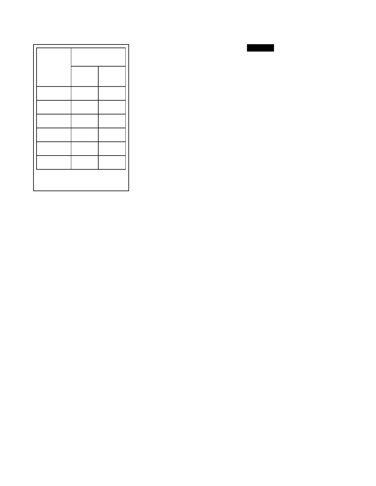
Step 3. Using crossdraw sequence
to assure uniformity, wrench-tighten
Long Hex Bolts and Short Hex Bolts
to appropriate torque values. Repeat
crossdraw sequence two to three
times at incremental torque valves
until reaching the torque valves found
in Table B.
Step 4. Inspect to assure all Hex Bolts
are securely tightened.
Step 5. Using the union, secure the
PRV-1
A to the Diaphragm cover.
Step 6. Using the union, secure the
PRV-1
A trim.
Step 7. Ensure that the unions and
pipe nipples flare fittings are securely
tightened.
Pilot Valve Replacement
Prior to removing the Pilot Valve, the
Model PRV-1
A Valve must be taken
out of service and completely drained.
When installing the replacement Pilot
Valve, the trim components must be
replaced exactly as they were. After
reinstalling the Pilot Valve and before
returning the Model PRV-1
A Valve
into service, completely unscrew the
Adjusting Screw of the replacement
Pilot Valve so as to obtain a minimum
outlet “set pressure”. Then proceed to
use the instructions under Placing The
Valve In Service section to place the
Model PRV-1
A Valve in service.
NOTICE
The Pilot Valve is not field repairable.
Attempting to repair the Pilot Valve may
render the valve ineffective and impair
the system operation.
Completely unscrewing the Adjusting
Screw of the replacement Pilot Valve
will help to avoid an accidental over
pressurization of the system piping
prior to achieving the desired “set
pressure”.
Strainer Maintenance
Prior to performing strainer mainte-
nance, the Model PRV-1
A Valve must
be taken out of service and completely
drained. Be prepared for small amounts
of residual liquid when disconnecting
any trim part. See Figures 4 and 5 to
identify parts and key features.
Step 1. Loosen the compression fitting
on the supply line.
Step 2. Disconnect the compression
fitting on the supply line at the strainer
outlet and swing the supply line away
for access.
Step 3. Remove the inlet pressure
gauge and trim as sub-assembly from
the strainer outlet.
Note: When removing, do not grip the
gauge itself, loosen the sub-assembly by
wrench on the fitting closest to strainer
only.
Step. 4 Remove the strainer from the
valve body.
Step 5. Disassemble the strainer for
cleaning. Remove the end lock washer
and slide the screen off the strainer
body. Clean the screen and body.
Step 6. Reassemble the screen onto
the body and secure with a lock
washer.
Note: Prior to installing the strainer and
gauge and trim sub-assembly, clean all
exposed male NPT pipe threads and apply
TEFLON tape as required. Do not apply
sealant to male threads of the separated
compression fitting. Do not contaminate
the strainer screen.
Step 7. Install the strainer into the valve
body. Install the gauge and the trim
sub-assembly into the strainer outlet.
Step 8. Reconnect the supply line
compression fitting to the strainer
outlet trim and tighten the compres-
sion fitting on the supply line.
For more information on how to place
the Model PRV-1
A Valve in service, see
the Placing the Valve in Service section.
Nominal
Valve Sizes
ANSI
Inches
(DN)
Torque
lb-ft
(N∙m)
Nuts
Short
Hex
Bolts
1 1/2
(40)
44
(59,7)
35
(47, 5)
2
(50)
44
(59,7)
35
(47, 5)
3
(80)
188
(254,9)
150
(203,4)
4
(100)
396
(536,9)
316
(428,4)
6
(150)
265
(359,3)
212
(287,4)
8
(200)
545
(738,9)
436
(591,1)
TABLE B
DIAPHRAGM COVER BOLTS
MINIMUM TORQUE
 Loading...