TFP1581
Page 6 of 14
Technical
Data
Approvals
UL and C-UL Listed (2 in. to 6 in. only)
FM Approved
The UL Listing is based on the following
factors:
• Installation requirements referenced in
the Standard for Installation of Sprinkler
Systems, NFPA 13, or the Standard
for Installation of Standpipe and Hose
Valves, NFPA 14, as applicable.
• Inspection, testing, and maintenance
requirements referenced in the
Standard for Inspection, Testing, and
Maintenance of Water-Based Fire
Protection Systems, NFPA 25.
• Filed-setting of the Model PRV-1
A Valve
to provide required outlet pressures and
flows for the given application.
• Testing of the Model PRV-1A Valve after
installation in accordance with NFPA 13
and/or NFPA 14 as applicable.
• Testing the Model PRV-1A Valve
periodically thereafter in accordance
with NFPA 25.
Note: UL/C-UL Approval is based on the
use of the 3/4 in. CLA-VAL Model 55L-60
pressure relief valve.
Maximum Inlet Pressure
300 psi (20,7 bar)
Factory Outlet “Set Pressure”
125 psi (8,6 bar)
Field Outlet “Set Pressure” Range
90 to 175 psi (6,2 to 12 bar)*
* = Sizes 2, 3, 6 and 8 in. are rated to a set pres-
sure of 80 to 175 psi (5,5 to 12 bar)
Pressure Loss With Inlet Pressure
Above “Set Pressure”
The inlet pressure minus the outlet “set
pressure” equals pressure loss. For
example, assuming that the inlet flowing
pressure is 225 psi (15,5 bar) and the field
outlet “set pressure” is 130 psi (9,0 bar),
the pressure loss is 95 psi (6,5 bar).
Pressure Loss with Inlet Pressure
Below “Set Pressure”
See Graphs A to E. These graphs are a
requirement of UL and should be used as
reference only.
Rated Flowing Range
2 in. .................. 25 to 250 gpm
(DN50) ............... (95 to 946 Lpm)
3 in. .................. 25 to 500 gpm
(DN80) ..............(95 to 1893 Lpm)
4 in. ................. 25 to 1000 gpm
(DN100) .............(95 to 3785 Lpm)
6 in. ................. 25 to 1300 gpm
(DN150 ) .............(95 to 4920 Lpm)
8 in. ................100 to 4000 gpm
(DN200) ............(379 to 15141 Lpm)
Note: Rated flowing range is the flow range
tested by the approval agencies. All valves
are leak tight and are capable of operating
at 0 gpm (0 Lpm).
End Connections
• Flanged end connections are available
as drilled per Table A.
• Grooved end connections follow
industry standard groove specifications.
Valve Materials of Construction
See Figure 3
Body
Epoxy-coated ductile iron per ASTM
A536-77, Grade 65-45-12
Diaphragm Cover
Epoxy coated ductile iron per ASTM
A536-77, Grade 65-45-12
Diaphragm
Polyester fabric-reinforced, TEFLON
coated, EPDM rubber per ASTM D2000
Diaphragm Cover Fasteners
Aluminium-zinc coated steel
Trim Materials of Construction
See Figure 7
Pilot Valve
Cast bronze and stainless steel with fabric
reinforced, EPDM rubber per ASTM D2000
diaphragm
Pressure Gauges
3 3/4 in. (95 mm) diameter, UL and FM
listed, 0 to 300 psi (0 to 20,7 bar)
Strainer, Tube, and Fittings
Stainless steel
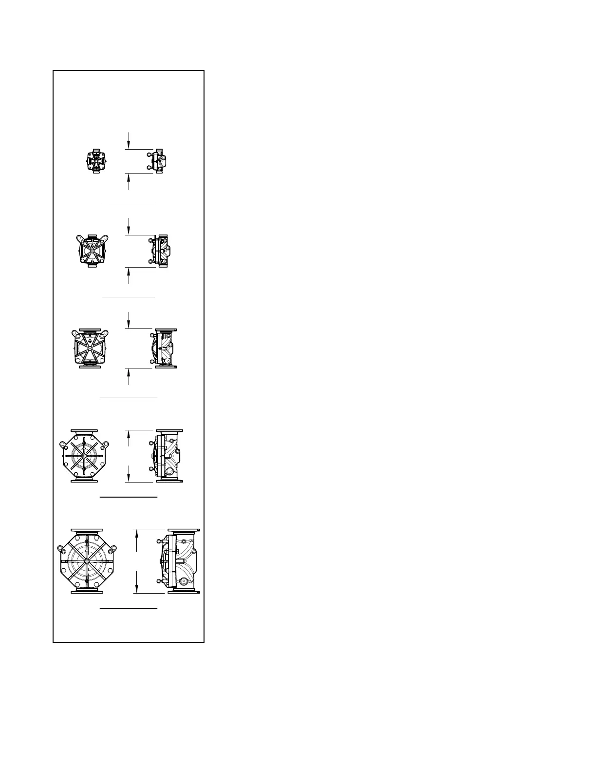
8 Inch (DN200)
6 Inch (DN150)
4 Inch (DN100)
3 Inch (DN80)
2 Inch (DN50)
22-3/8"
(569 mm)
16-3/4"
(425 mm)
13-3/4"
(349 mm)
10-3/16"
(260 mm)
27-7/16"
(697 mm)
ARE APPLICABLE TO
ALL END CONNECTION
CONFIGURATIONS
AVAILABLE PER
VALVE SIZE
FIGURE 6
PRV-1
A VALVE
TAKE-OUT DIMENSIONS