TFP1581
Page 3 of 14
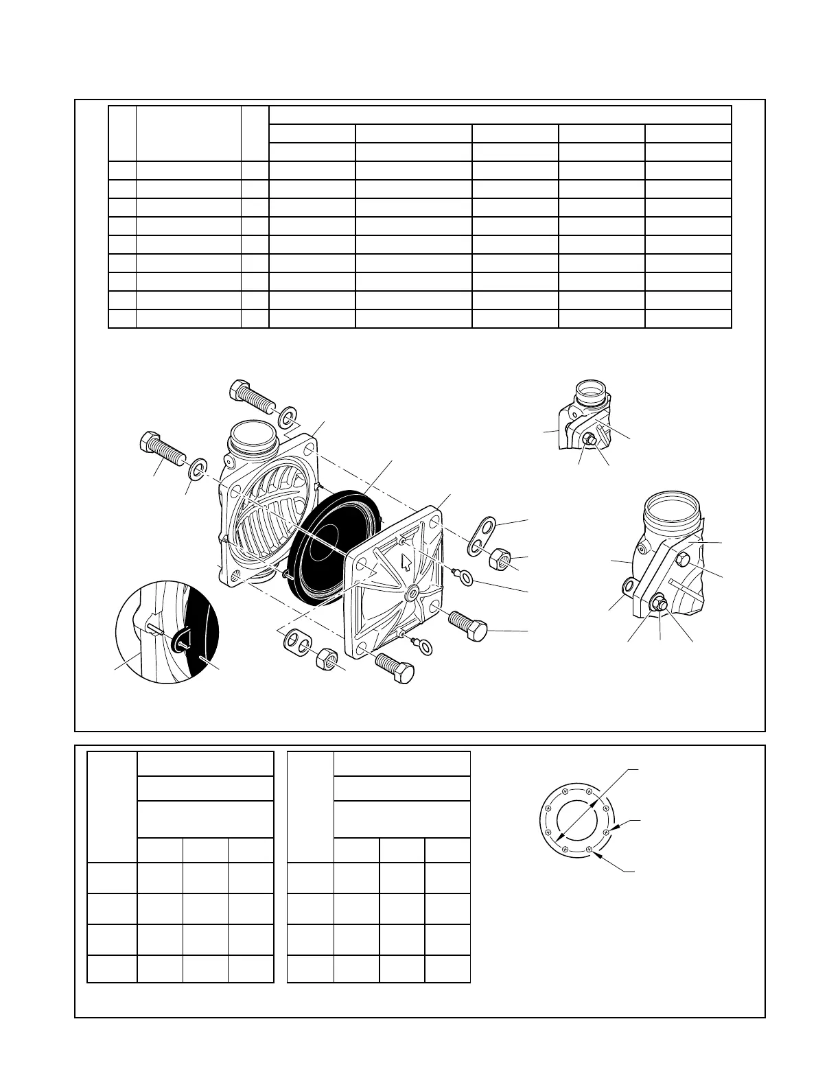
Item Description Qty.
Nominal Valve Size ANSI Inch (DN)
2 (DN50) 3 (DN80) 4 (DN100) 6 (DN150) 8 (DN200)
P/N P/N P/N P/N P/N
1 Valve Body 1 N/R N/R N/R N/R N/R
2 Diaphragm 1 545000020 545000030 545000040 545000060 545000080
3 Diaphragm Cover 1 N/R N/R N/R N/R N/R
4 Hex Bolt, Short 2
a
545100001 545100002 545100003 545100004 545100003
5 Hex Bolt, Long 2 545100011 545100012 545100013 545100014 545100015
6 Lift Washer 2
b
N/A 545100021 545100022 545100023 545100022
7 Hex Nut 2 545100031 545100032 545100033 545100034 545100033
8 Hoist Ring 2 545100041 545100041 545100041 545100041 545100041
9 Flat Washer 2 N/A 545100024 545100025 545100026 545100025
NOTES:
a. Hex Bolt, Short, Qty. 6 in 6 and 8 inch (DN150 and DN200) assemblies
b. Lift Washer not used in 2 inch (DN50) assembly
c. N/R = Not Replaceable
d. Order replacements parts only via Part Numbers given, do not
replace Hex Bolt, Hex Nut, Lift Washer or Hoist Ring with com-
mon hardware parts
Nominal
Valve
Size
ANSI
in.
(DN)
Flange Drilling
Specification
Nominal Dimensions in.
(mm)
ANSI B16.1
a
(Class 125)
A B N
3
(80)
6.00
(152,4)
0.75
(19,0)
4
4
(100)
7.50
(190,5)
0.75
(19,0)
8
6
(150)
9.50
(241,3)
0.88
(22,2)
8
8
(200)
11.75
(298,5)
0.88
(22,2)
8
NOTES:
a. Same drilling as for ANSI B16.5 (Class 150)
and ANSI B16.42 (Class 150)
b. Same drilling as for BS 4504 Section 3.2 (PN16)
and DIN 2532 (PN16)
Nominal
Valve
Size
ANSI
in.
(DN)
Flange Drilling
Specification
Nominal Dimensions in.
(mm)
ISO 7005-2
(PN16)
b
A B N
3
(80)
6.30
(160,0)
0.75
(19,0)
8
4
(100)
7.0 9
(180,0)
0.75
(19,0)
8
6
(150)
9.45
(240,0)
0.91
(23,0)
8
8
(200)
11.61
(295,0)
0.91
(23,0)
12
2 INCH
VALVE ONLY
6 AND 8 INCH
79
5
6
1
7
5
3
1
2
5
9
1
2
3
8
4
7
6
Bolt Circle
Diameter
Dim. B
Bolt Hole
Diameter
Qty. N
FIGURE 3
DV-5
A VALVE ASSEMBLY AND REPLACEMENT PARTS
(See Figure 7 For PRV-1A Trim Assembly)
TABLE A
FLANGE DRILLING SPECIFICATIONS