V46SA
Issue 27/02/02
© 1997 Johnson Controls, Inc.
Catalogue Section 7
Order No. PD-V46SA-E
3
For water the following formulae can be used to
calculate the quantity of water (Q in m3/h) or
the pressure drop across the valve (∆p in bar).
K
v
=
Q
p
∆
p =
Q
K
v
()
2
Q =
pK
v
•
The (V46SA) K
v
-value= 0.5
The Kv factor is the quantity of 20°C water that
will pass through the valve at one bar pressure
drop and maximum valve opening.
Note
If the compressor operates in a high
ambient temperature, the refrigerant
pressure may at times remain high enough
to cause the valve to partly open when the
compressor is idle. In such conditions the
valve opening point should be raised just
enough to cause the valve to close during
compressor standby periods. Take this into
account when flow is calculated..
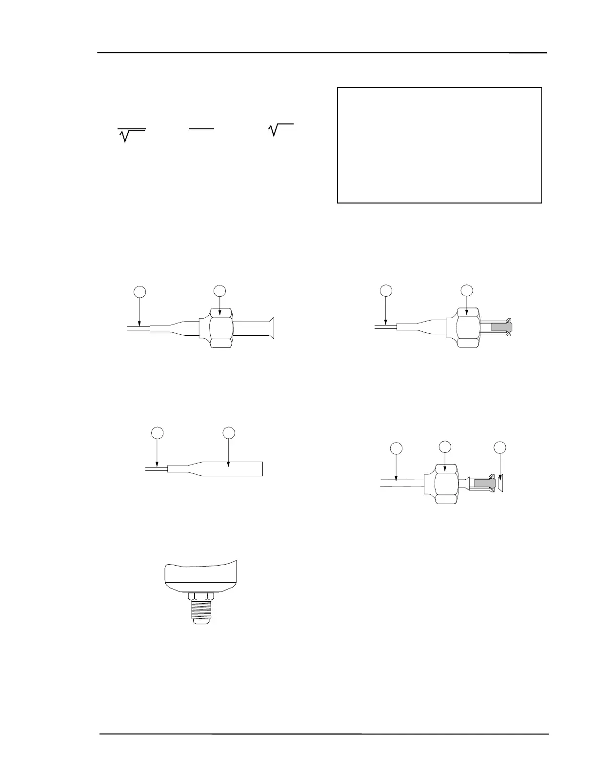
Pressure Connections
In the valve selection table the following connection styles are given.
1
2
Fig. 3
Style 13 (excl. valve depressor)
1
. 75 cm capillary
2. 7/16-20 UNF flare nut
2a
1
Fig. 4
Style 34
1
. 75 cm capillary
2. 1/4" tube for braze connection
Fig. 5
Style 5
7/16-20 UNF
1
2
Fig. 6
Style 45A (incl. valve depressor
mounted into flare)
1
. 75 cm capillary.
2. 7/16 - 20 UNF flare nut.
1
3
2
Fig. 7
Style 50 (incl. valve depressor mounted
into machined flare)
1
. 75 cm capillary.
2. 7/16 - 20 UNF flare nut.
3
. copper sealring