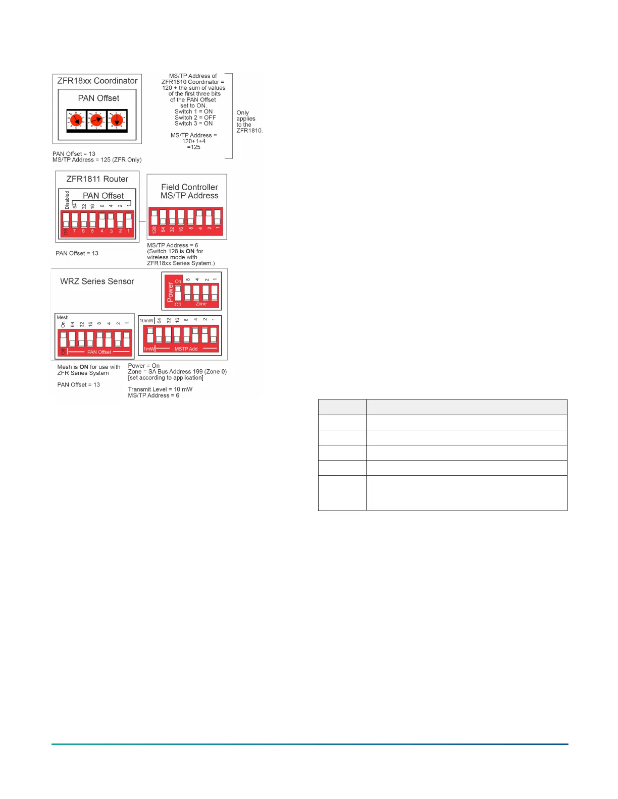
Figure 7: Sample DIP switch settings
For a one-to-one network application with
a WRZ-7860 receiver, set the DIP switches
as indicated in Figure 7, and ensure that the
AREA and TRANSMITTER ID switches on the
WRZ-7860 Receiver and the WRZ Series Sensors
are set to the same value. See Figure 5.
a. Set the POWER switch to OFF.
b. Set the MODE switch to 1-to-1.
c. Set the SENSOR # to 199 for applications
with only one sensor per controller. Use
the other settings for additional sensors in
applications with a single controller performing
temperature averaging or high/low selection
in a zone. Refer to the WRZ Series one-to-
one Wireless Room Sensing System Technical
Bulletin (LIT-12011641) for information on
commissioning multiple WRZ Series Sensors
in a WRZ Series one-to-one Wireless Room
Sensing System.
d. Set the AREA switches to match the AREA
switch on the WRZ-7860 Receiver.
e. Set the Transmitter ID switches to match the
Transmitter ID on the WRZ-7860 Receiver.
3. Install the two supplied AA alkaline batteries
into the battery compartment on the back of the
sensor. Ensure to install the batteries in the correct
polarity. See Figure 6.
4. If the address DIP switches are set to the correct
positions and the temperature sensing system is
ready for operation or testing, set the POWER DIP
switch to the ON position. See Figure 4 or Figure 5.
Five seconds after the application of power, the red
LED flashes to indicate the firmware revision. For
example, three flashes of the red LED during the
startup process indicates firmware revision 3.
5. Align the tabs on the bottom edge of the mounting
base with the slots on the bottom edge of the
sensor housing, and rotate the sensor assembly
onto its mounting base. Reverse the procedure
shown in Figure 3.
6. Use a 1.6 mm (1/16 in.) Allen wrench or Johnson
Controls T-4000-119 Allen-Head Adjustment Tool to
tighten the tamper-resistant set screw and secure
the sensor assembly onto its mounting base. See
Figure 3.
Testing signal strength
When the WRZ sensor communicates with the ZFR or
ZFR Pro Series Router, or WRZ-7860 Receiver, press and
release the manual occupancy override button to display
signal strength.
Press and hold the manual occupancy override button
on the WRZ Series Sensor for 5 seconds or more to place
the sensor into Rapid Transmit Mode and initiate a signal
strength test with the associated ZFR or ZFR Pro Series
Router, or WRZ-7860 Receiver. See Figure 1 and Rapid
Transmit Mode for additional information.
Table 1: WRZ Sensor to ZFR or ZFR Pro Series router, or
WRZ-7860 Receiver wireless signal strength
Flashes Signal strength
3 Excellent/Sensor has joined network
2 Good/Sensor has joined network
1 Weak/Sensor has joined network
0 None/Sensor has not joined network
Fast
flash
rate (8)
Unable to locate associated wireless-enabled
field controller
On LCD models, the signal strength shows on the display
on the face of the sensor as shown in Figure 8.
WRZ Series Wireless Room Sensors Installation Guide 5
 Loading...