5168275-JIM-I-1121
10 Johnson Controls Ducted Systems
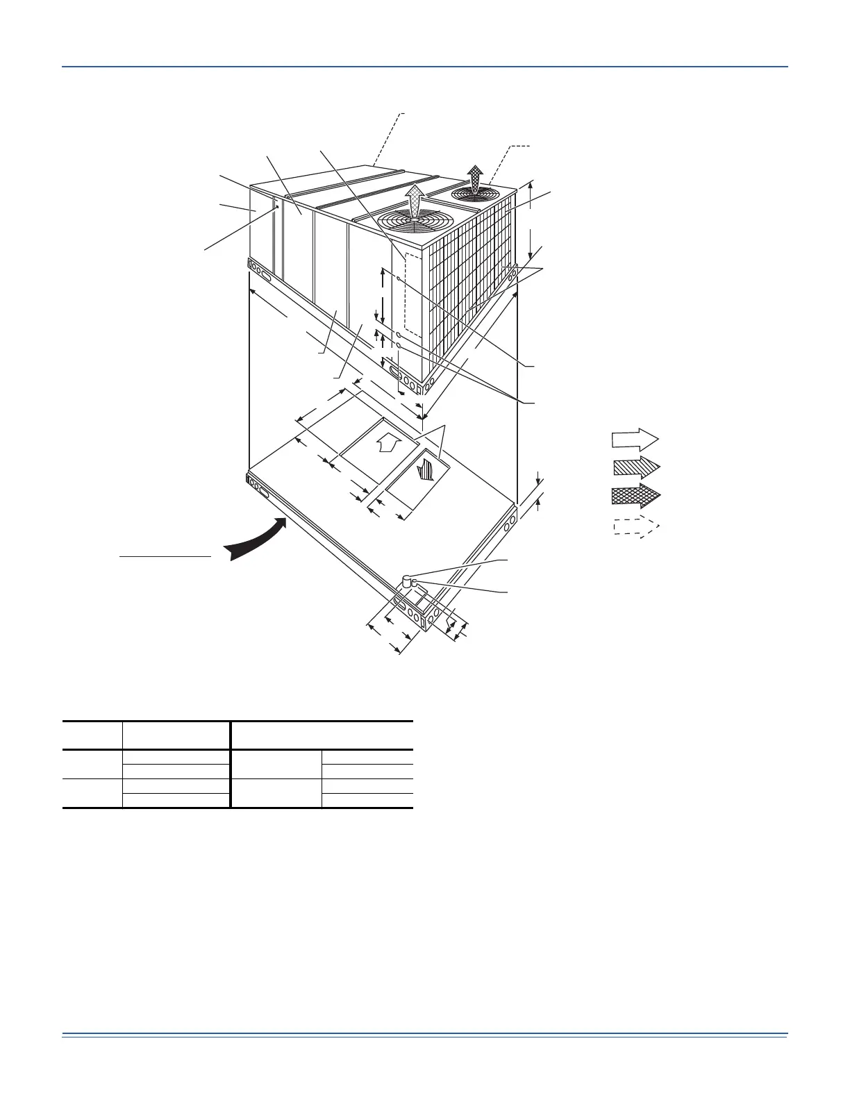
Figure 8: J15XP Unit Dimensions Front View
NOTE: All entry holes should be field sealed to prevent rain
water entry into the building.
Utilities Entry
Hole
Opening Size
Diameter
Used For
A
1-1/8” KO
Control Wiring
Front
3/4” NPS (Fem.) Bottom
B
3-5/8” KO
Power Wiring
Front
3” NPS (Fem.) Bottom
RETURN
AIR
SUPPLY
AIR
BOTTOM SUPPLY
AND RETURN
AIR OPENINGS
(See Note)
(B)
POWER WIRING
ENTRY
(A)
CONTROL WIRING
ENTRY
NOTE:
For curb mounted units, refer to the curb hanger
dimensions of the curb for the proper size of the
supply and return air duct connections.
UNIT BASE WITH RAILS
Shown separately to illustrate
Bottom Duct openings and Power
Connection locations
12-1/2"
9-1/4"
8-1/8"
9-3/4"
3-3/4"
(B)
POWER WIRING
ENTRY
(A)
CONTROL WIRING
ENTRY
92"
CONDENSER
COILS
OPTIONAL COIL
GUARD KIT
52-5/8"
COMPRESSOR
ACCESS
(See detail "X")
ECONOMIZER / MOTORIZED DAMPER,
FIXED OUTDOOR INTAKE AIR AND
POWER EXHAUST RAIN HOODS
(See detail "Y")
FIELD-SUPPLIED
DISCONNECT SWITCH
LOCATION
BLOWER
ACCESS
BLOWER MOTOR
ACCESS
BLOWER
COMPARTMENT
ACCESS
(Auxiliary)
DOT PLUG
(For pressure
Drop Reading)
FRONT
VIEW
ELECTRIC HEAT
ACCESS
CONTROL BOX
ACCESS
136-1/4"
21"
5"
9-3/4"
11-1/2"
2-3/4" 21-1/2"
33"
35"
5-7/8"
35-1/4"
RETURN AIR
SUPPLY AIR
OUTDOOR A IR
OUTDOOR A IR
(Economizer)
OPTIONAL
 Loading...