5168275-JIM-I-1121
6 Johnson Controls Ducted Systems
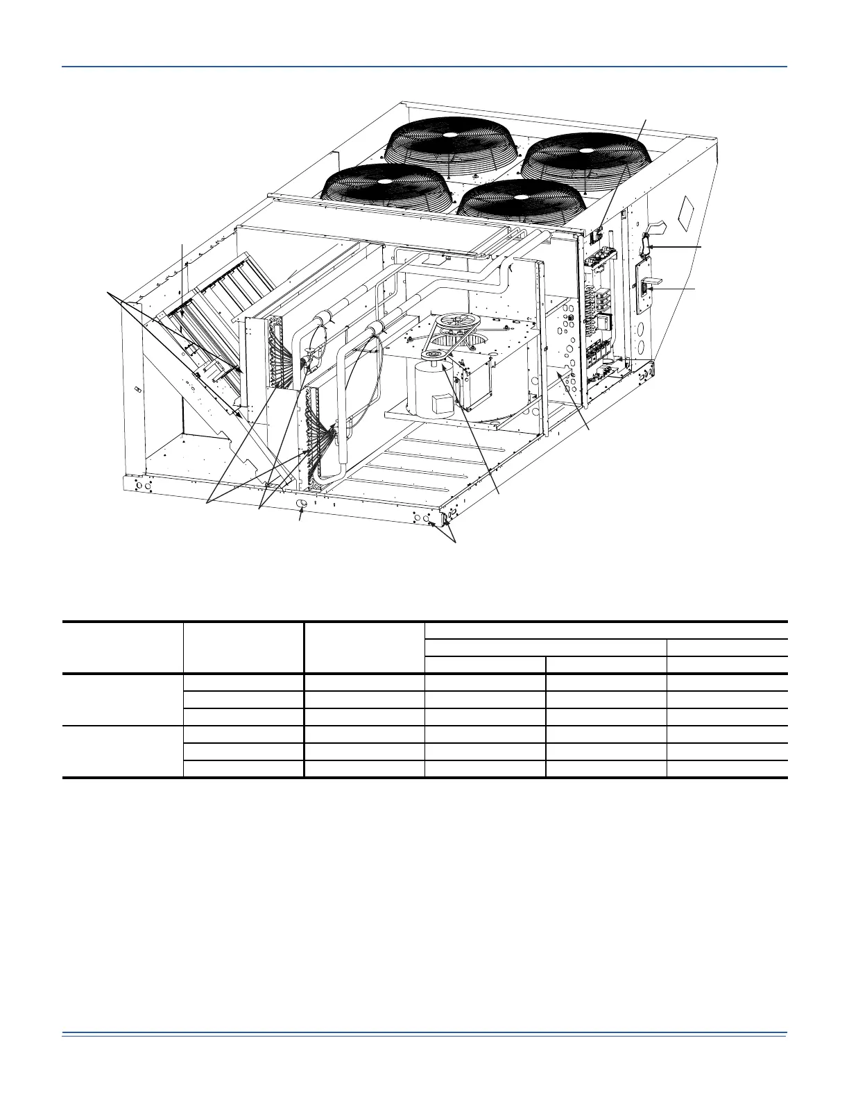
Figure 1: J20XP Component Location
Table 1: J15/20XP Unit Limitations
Size
(Tons)
Unit Voltage SCCR (kVA)
Unit Limitations
Applied Voltage Outdoor DB Temp
Min Max Max (°F)
15
(15)
208/230-3-60 5 187 252 125
460-3-60 5 432 504 125
575-3-60 5 540 630 125
20
(20)
208/230-3-60 5 187 252 125
460-3-60 5 432 504 125
575-3-60 5 540 630 125
Smart Equipment™ Control Board
110 Volt Convenience
Outlet (“Powered” or
“Non-Powered” Optional)
Disconnect Location
(Optional Disconnect Switch)
Bottom Power and
Control Wiring Entry
Electric Heater Location
(Electric Heat Offered as a Field-Installed Accessory Only)
Belt Drive
Blower Motor
14 Gauge
Base Rails
with Lifting Holes
1” NPT
Condensate Drain
Thermal
Expansion
Valve
Copper Tube/
Aluminum Fin
Evaporator
Coils
2” Disposable Filters
(4” Filters Optional)
Slide In/ Plug In
Internal Economizer
(Optional)
 Loading...