5168275-JIM-I-1121
34 Johnson Controls Ducted Systems
Air Balance
Start the supply air blower motor. Adjust the resistances in both
the supply and the return air duct systems to balance the air
distribution throughout the conditioned space. The job
specifications may require that this balancing be done by
someone other than the equipment installer.
To check the supply air CFM after the initial balancing has been
completed:
1. Remove the two 5/16” dot plugs from the blower motor and
the filter access panels shown in the Unit Dimensions Front
View (Figures 7 and 8) and Unit Dimensions Rear View
(Figure 9), respectively.
2. Insert at least 8" of 1/4 inch tubing into each of these holes
for sufficient penetration into the air flow on both sides of
the indoor coil.
NOTE: The tubes must be inserted and held in a position
perpendicular to the air flow so that velocity pressure
will not affect the static pressure readings.
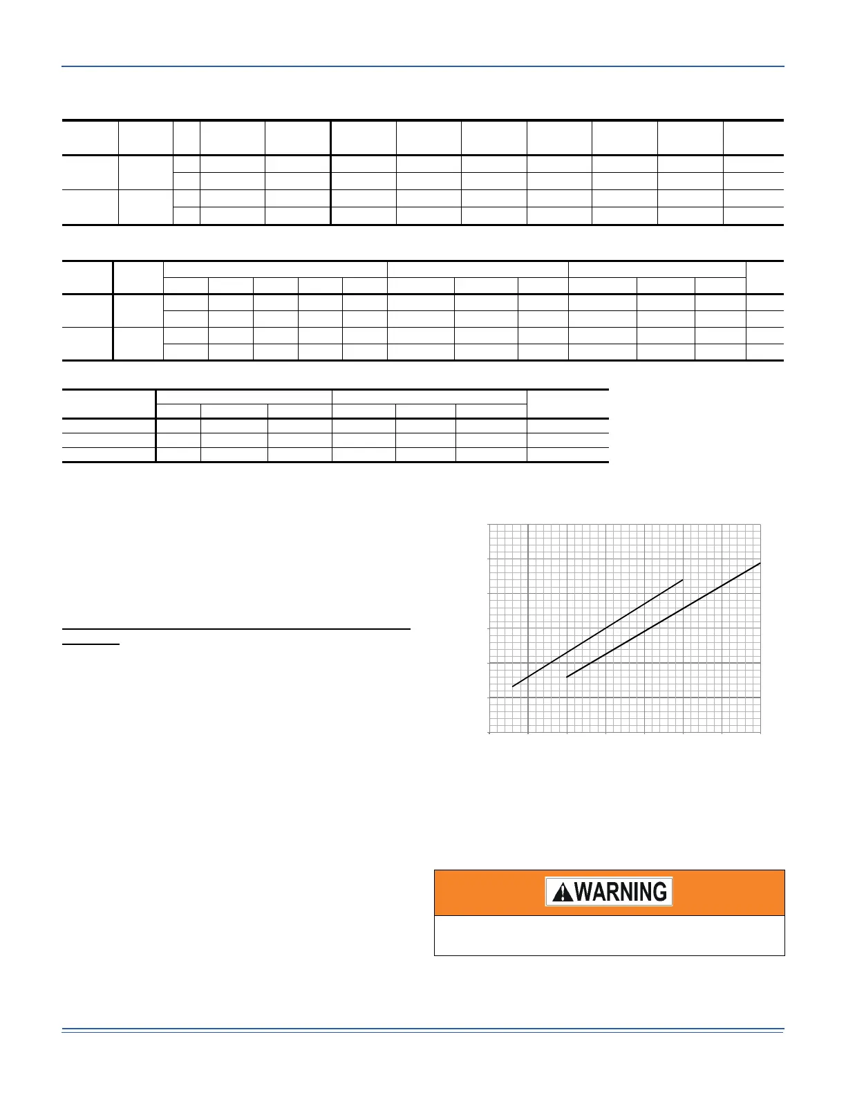
3. Using an inclined manometer, determine the pressure drop
across a dry evaporator coil. Since the moisture on an
evaporator coil may vary greatly, measuring the pressure
drop across a wet coil under field conditions would be
inaccurate. To assure a dry coil, the compressors should
be deactivated while the test is being run.
Figure 19: Pressure Drop Across A Dry Indoor Coil Vs.
Supply Air CFM For All Unit Tonnages
4. Knowing the pressure drop across a dry coil, the actual
CFM through the unit can be determined from the curve in
Pressure Drop vs. Supply Air CFM Figure 19.
After readings have been obtained, remove the tubes and
reinstall the two 5/16” dot plugs that were removed in Step 1.
Table 13: RPM Selection
Size
(Tons)
Model HP
Motor
Sheave
Blower
Sheave
6 Turns
Open
5 Turns 4 Turns 3 Turns 2 Turns 1 Turns Fully
Open Open Open Open Open Closed
15
J**XP
5 1VP60 BK120 700 730 760 790 820 850 880
(15) 7.5 1VP60 BK100 845 885 925 960 1000 1035 1070
20
J**XP
7.5 1VP60 BK110 765 800 835 870 900 935 965
(20) 10 1VP60 BK090 930 970 1010 1050 1090 1130 1170
Table 14: Indoor Blower Specifications
Size
(Tons)
Model
Motor Motor Sheave Blower Sheave
Belt
HP RPM Eff. SF Frame
Datum Dia.
Bore (in) Model
Datum Dia.
Bore (in) Model
15
(15)
J**XP
5 1750 0.895 1.15 184T 4.5 - 5.7 1-1/8 1VP60 11.4 1-3/16 BK120 BX81
7.5 1750 0.91 1.15 213T 4.5 - 5.7 1-3/8 1VP60 9.4 1-3/16 BK100 BX78
20
(20)
J**XP
7.5 1750 0.91 1.15 213T 4.5 - 5.7 1-3/8 1VP60 10.4 1-3/16 BK110 BX78
10 1760 0.895 1.15 215T 4.5 - 5.7 1-3/8 1VP60 8.4 1-3/16 BK090 BX75
Table 15: Power Exhaust Specifications
Voltage
Motor Motor
CFM @
0.1 ESP
HP RPM
1
1. Motors are multi-tapped and factory wired for high speed.
QTY LRA FLA MCA
208/230-1-60 3/4 1075 1 7.7 5.0 6.25 5250
460-1-60 3/4 1075 1 4.1 2.2 2.75 5250
575-1-60 3/4 1050 1 2.84 1.5 1.875 5250
Failure to properly adjust the total system air quantity
can result in extensive blower damage.
0.00
0.10
0.20
0.30
0.40
0.50
0.60
3000 4000 5000 6000 7000 8000 9000 10000
Pressure Drop (IWG)
Nominal Air Flow (CFM)
Pressure Drop Across a Dry Coil vs Supply Air CFM
J15XP
J20XP
 Loading...