12 ©2010 Johnson Level & Tool - Rev. 1
2. Components
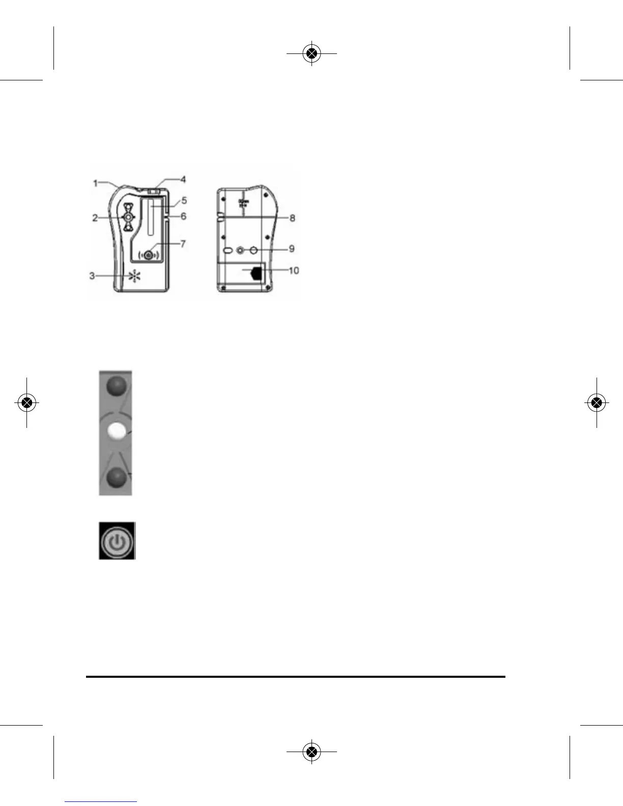
(a) Structure
1. Holding Cord
2. Signal Indicator
3. Horn
4. Horizontal Vial
5. Detecting Window
6. Reference Front Marker
7. Power Key
8. Back Reference Marker
9. Connection Port
10. Battery Door
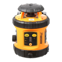
(b) Display
When first turning the detector on, the middle signal
indicator turns red first and then turns green. If the horn
gives two short sounds and the unit powers off
automatically, it means that the battery voltage is
seriously low and it is necessary to replace the battery
immediately. When turning the power on and the down
signal indicator flashes, it means that the battery is low
and it is necessary to replace the battery.
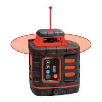
Power Key: Turn on/off the instrument
3. Battery Installation
1. Open the battery cover and put the batteries into the battery
case according to the polarity shown in the battery slot.
2. Snap the battery cover back.
3919H_Manuals 10/12/10 10:31 AM Page 12