OWNER'S MANUAL
M K
M K
6
7
ROWER
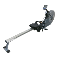
Step A.
Taking the plug cable of the
console and inserting to the
console mounting.
Step B.
Insert the console to the
console mounting bracket,
which attached on the front
of frame.
Step C.
Aim the two holes on sides of
console to the bracket's two
screw holes, then use two
bolts to secure.
CONSOLE ASSEMBLY (See Fig.6)
Fig.6
Step A.
Insert two size "A A" 1.5V
batteries or two Size "UM-3"
1.5V batteries into the battery
Compartment and make sure
that the polarity ("+" or "-") is
positioned as indicated in the
batter y compartment.
Step B.
Install the two batteries in the
batter y compartment.
CONSOLE ASSEMBLY (See Fig.7)
Fig.7
Step A.
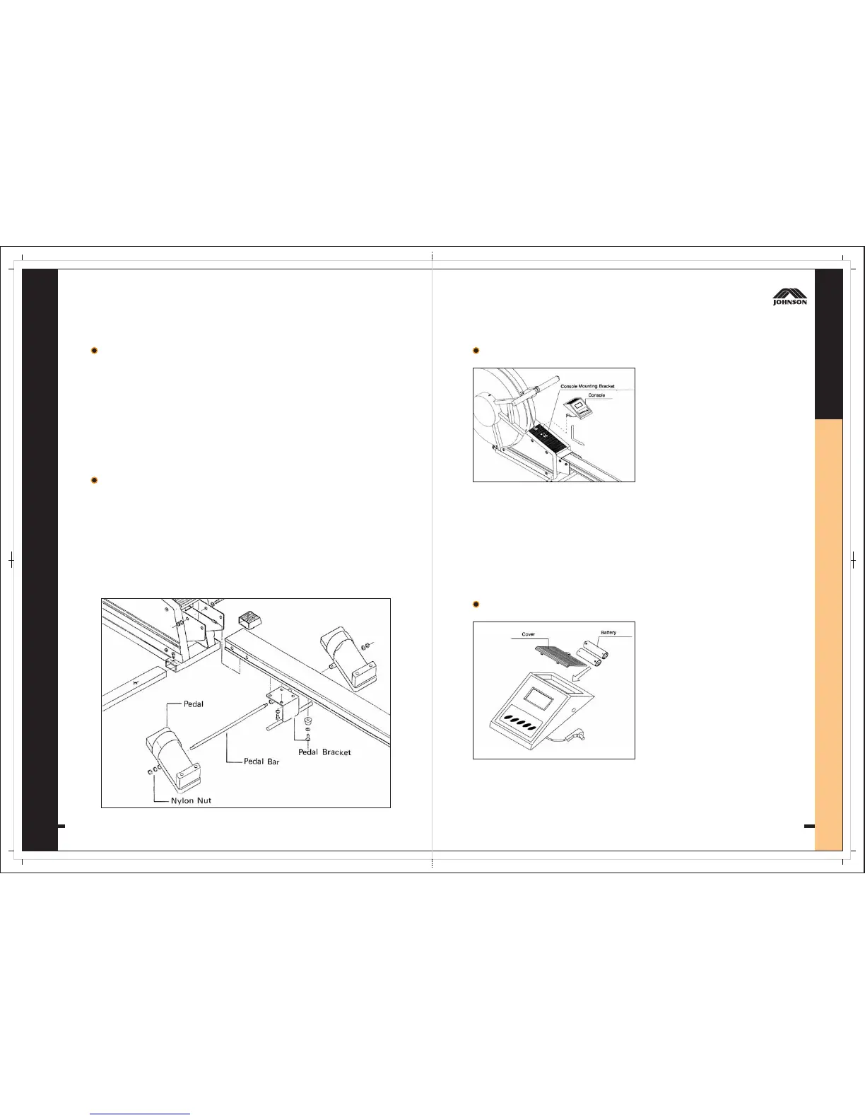
Insert the pedal bar into the tube of pedal bracket in even length both side.
Step B.
Assemble Lef t & Right Side pedal.
Step C.
Using Washer and nylon nut to fasten.
PEDAL ASSEMBLY (See Fig.5)
Fig.5
The washer using here is the more bigger size washer 3/8 x Ø23 mm.
NOTE