3. Electrical systems
• Rudder pedal controller or SCC (optionally installed)
• Bug wiper system
• Heated boots
• 5V power supply
• Warning systems (if fitted)
Dividing the avionics and electrical system in separate systems allows
the pilot to supply power from separate batteries or from the same
source.
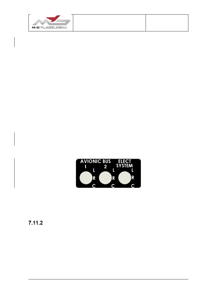
Battery selection for the avionics and electrical systems are on a
separate switch arrangement, allowing selection between the Battery 1
(L), Battery 2 (R) and centre (C) and or the auxiliary battery (C) (if
installed).
Figure 7.11-2
NOTE: The switch layout as given in Figure 7.11-2 may differ
depending on customised electrical layout.
Power plant electrical system description
Power to the Jet system can be selected from either the left or right
battery. This is achieved by selecting the appropriate battery on the Jet
master switch arrangement.
Refer to JS-MD 3 Jet Sustainer Flight Manual Supplement Section 7.2
for more information on the electrical system.
 Loading...