OPERATING MANUAL for
BRAKE UNITS
JB10/... JB16/... JB26/... JB40/... JB52/...
(Installation set)
JB
8 of 19
01.96/00/Scho
Mounting:
The JB brake unit can be
fastened to a mounting
plate by four screws.
8 NOTES ON CONNECTION AND USE
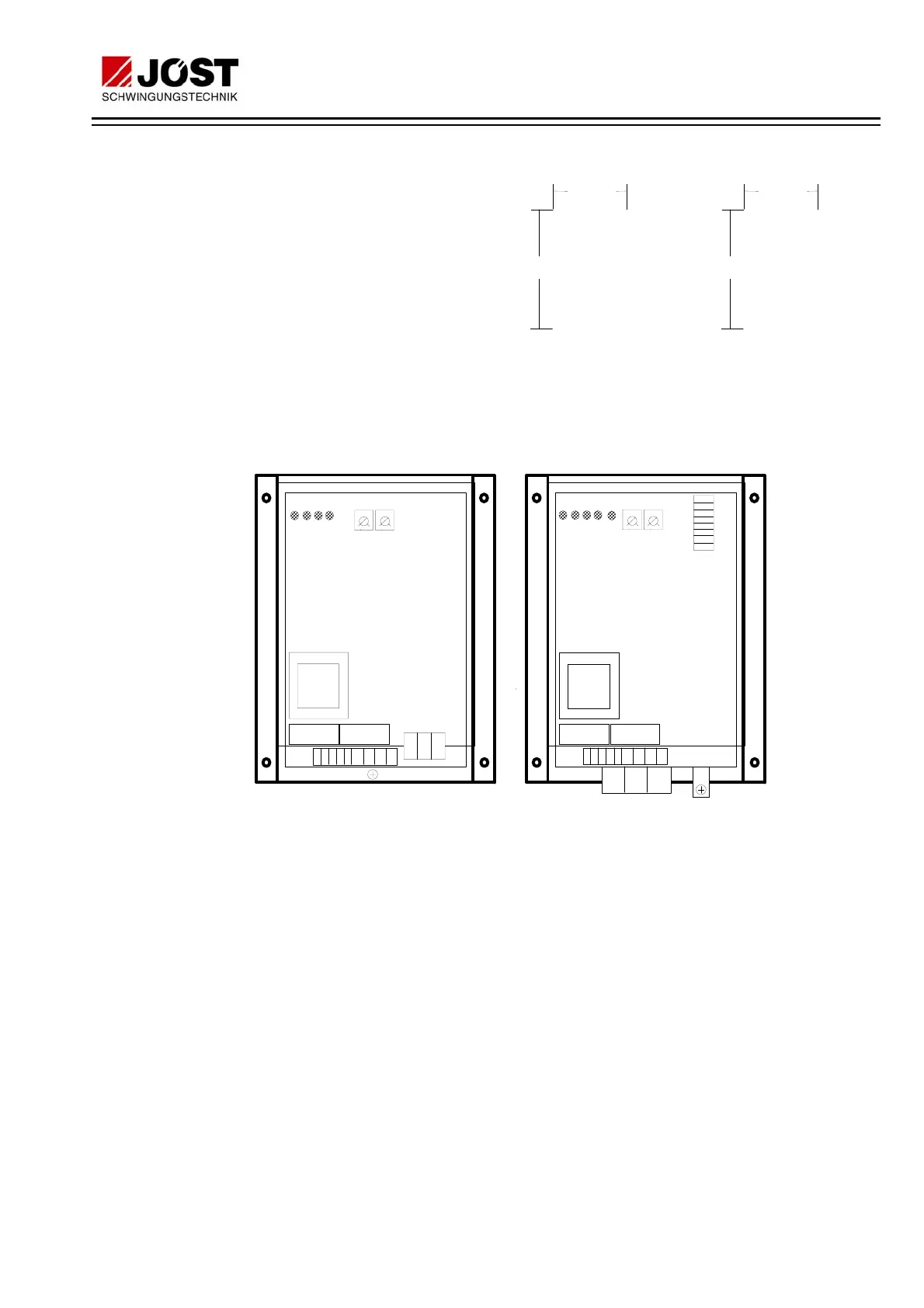
8.1 POSITION OF THE ADJ. ELEMENTS and COMPONENTS
PE
JB10/...E000
JB16/...E000
JB26/...E000
JB40/...E000
JB52/...E000
O
X1
X2
X1
X2
Bar
display
PE
8ab
34567n1
n2
n3n4
34567n1
n2
n3n4
8a b
T
P M B S
sec
I
Amp
T
P M B S
sec
I
Amp
Mains
trans-
former
Mains
trans-
former
8.2 CONNECTIONS
8, a : Mains connection
a, b : Brake current output
3, 4 : potential free make contact for actuating the brake contactor
6, 7 : Input "motor on". Connection for the potential free auxiliary
contact of the motor contactor
n2, n4 : Potential free break contact for actuating the motor contactor
n1 : "Standstill detector" input
PE : Protective earth conductor connection
The other terminals must not be connected.
Cross-section of connectable cable:
9-pole terminal strip X1: max. 1.5 mm
2
3-pole terminal strip X2: max. 4 mm
2
for JB10.., JB16..
max. 35 mm
2
for JB26.., JB40.., JB52..
Please refer to the connection diagram in the appendix for electrical
connections, or to the connection sheet packed with the unit.
O
Drilling plan: JB 10 and JB 16
Hole dia.: 4mm
144 mm
O
O
O
137 mm
O
Drilling plan: JB 26 and JB 52
Hole dia.: 6 mm
215 mm
O
O
O
130 mm
 Loading...