4 Installation
4.3 Connecting connection cable
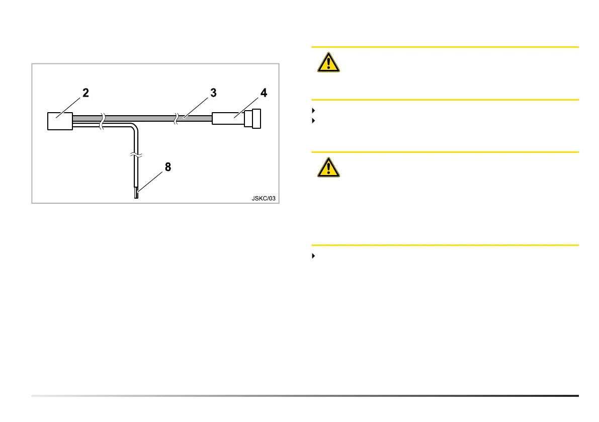
2 Plug (display)
3 Connection cable
4 Plug (fifth wheel coupling)
8 Power supply connection
– Black cable
Terminal 31 (negative) connection
– White cable
Terminal 15 connection (positive when ignition ON)
ATTENTION!
The safety information set out in section 2.2 must be
observed to prevent damaging the vehicle's electrical
system.
Connect the plug (2) to the display.
Route the power supply connection (8) to the point approved
by the vehicle manufacturer and connected there (see con-
nection diagram in section 4.1).
ATTENTION!
In order to avoid damage to the vehicle’s electrical and
sensor systems in the case of a short circuit, a commer-
cially available 1 A blade-type fuse must be installed in
the connection supply line (8). When making the con-
nection ensure that the display is suitable for the volt-
age of the vehicle (12 V or 24 V). Further information is
provided in the sales documentation.
Route the connection cable (3) to the fifth wheel coupling
and connect the plug (4) to the existing mating plug. The plug
must be locked with the yellow slide.
10 MUB 007 001 M01 (REV-C) 07/2020 Sensor JSK

 Loading...