11
ENGLISH
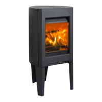
Fig. 11 Mounting of external air supply connection
1
2
1. Place the external air supply connection on the outside of
the external air supply adaptor.This works the same way
for both wall and fl oor outlet.
2. Tighten with screwdriver.
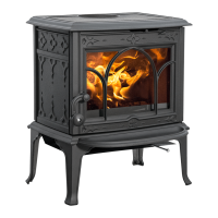
4.4 Location of approval label
Fig. 12 Approval label
A
1. The approval label (A) is located on the bottom of the
stove.
4.5 Chimney and fl ue pipe
• The fi replace must only be connected to a chimney and
fl ue pipe approved for solid fuel fi replaces with fl ue gas
temperatures as specifi ed in «2.0 Technical Data».
• For fl ue pipe dimension see “2.0 Technical Data”. NB:
The chimney’s diameter must be at least just as big as the
fl ue pipe.
• Connection to the chimney must be carried out in
accordance with the chimney supplier’s installation
instructions.
• Before a hole is made in the chimney, the product should
be test-mounted in order to correctly mark the position of
the fi replace and the hole in the chimney. See fi g. 1 for
minimum dimensions.
• Use a fl ue pipe bend with a sweep hatch to allow sweeping.
• Please note that it is extremely important for connections
to have a degree of fl exibility. This is to prevent any
movement in the installation leading to the formation of
cracks.
• For recommended chimney draught, see «2.0 Technical
Data».
NB! The minimum recommended chimney length is 3.5 m
from the fl ue pipe insert. If the draught is too strong, a fl ue
pipe damper can be installed and used to reduce the draugh
If a fl ue damper is fi tted it shall be of a type, which does not
block the fl ue totally. The damper shall be easy to operate and
incorporate an aperture within the blade, which in a continuous
area occupies at least 20 cm2 or 3 % of the cross-sectional
area of the blade if this is greater.
The position of the damper shall be recognizable from the
setting of the device.
If a draught regulator is fi tted the minimum cross sectional
area requirement shall not be applicable but the device shall
be easily accessible for cleaning.
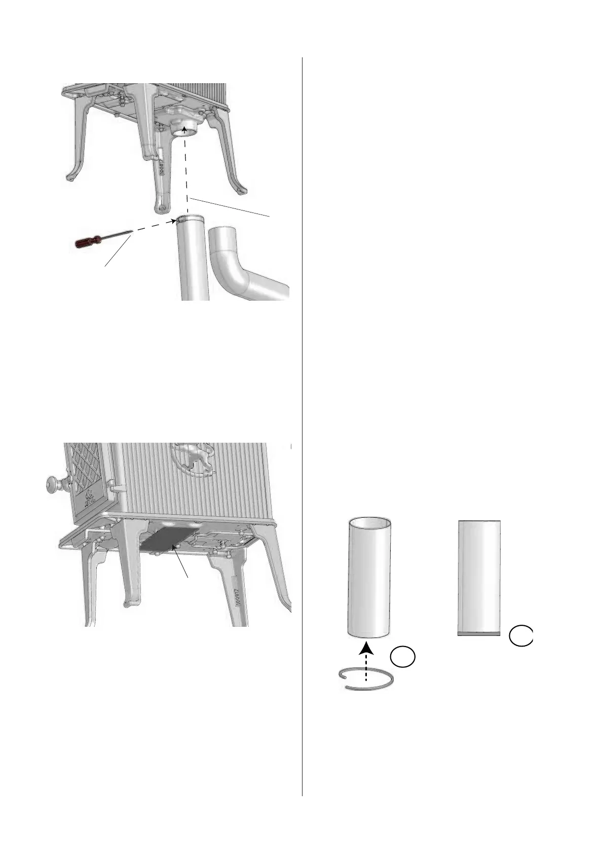
Assembly of fl ue pipe
The product is assembled for a top outlet as standard.
Fig. 13 Assembling the fl ue pipe
1
2
1. Pull off the protective paper from the supplied gasket
and attach it to the outside of the fl ue pipe
2. Insert the fl ue pipe into the smoke outlet.
Flue pipe is installed in the same way for top and rear outlet.
 Loading...