9.03.10
Height and stroke of the bobbin case opener
。
,
。
1.
2.
1 3
1
0.3 0.5 mm
Requirement
1 3
1
0.3
0.5
1. The top edges of the bobbin case opener and bobbin case should
be on one level.
2. when the bobbin case opener has deflected the bobbin case to its
furthest point, the catch of the bobbin case should be from to
mm from the back edge of the needle plate recess.
● ( )。
● 。
● ( )。
●
●
● .
1 1 2
2 1 2
1 2 Requirement 1
1 2 Requirement 2
Adjust bobbin case opener (screw ) in accordance with .
Turn the balance wheel until the bobbin case opener has deflected the
bobbin case to its furthest point.
Adjust bobbin case opener (screw ) in accordance with
,
。
,
。
9620
On the 9620 these
adjustments must be repeated
on the right post.
Depending on the thread size,
a variation of the setting in
Requirement is permitted.
2
2
9-14
Adjustment
9.05.05
Bevel gears for feed wheel drive
( 9610 9630 ) 、
、(on the 9610 9630)
Adjustment
9-49
()。
。
1.
2.
1
3 1 13 mm
Requirement
1
13 mm 3
1
1. the right side of bevel gear must be flush with its drive shaft (see
arrow).
2. there must be a distance of between bevel gear and bevel
gear .
● ( )。
● ( )。
●
●
1 1 2
2 3 4
1 2 Requirement 1
3 4 Requirement 2.
Adjust bevel gear (screws ) according to .
Adjust bevel gear (screws ) according to
9.03.13 9610 9630
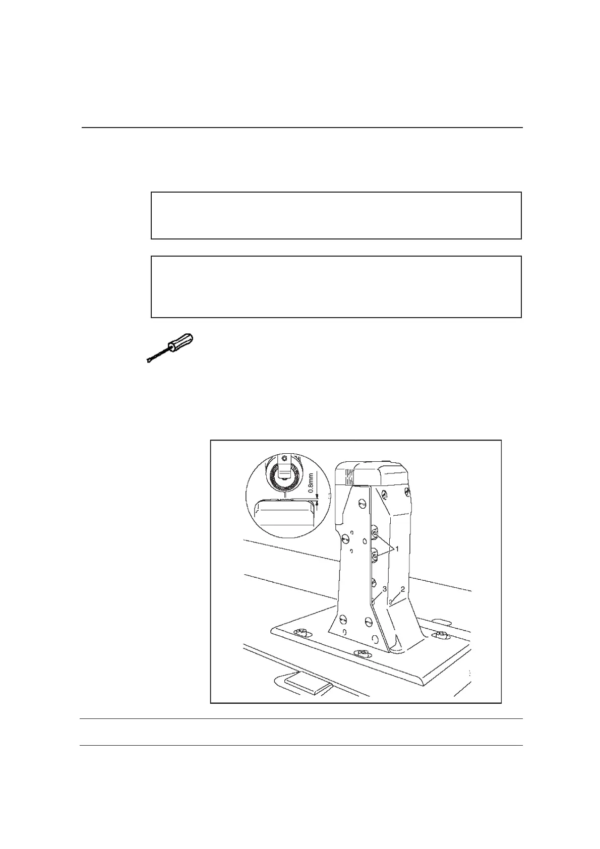
Height of the feed wheel on the 9610 9630
、
、
9.03.13 9610 9630
Height of the feed wheel on the 9610 9630
、
、
( )。0.8 mm
( )。0.8 mm
Requirement
0.8 mm
Feed wheel should protrude from the needle plate by tooth height (appro.
).
Requirement
0.8 mm
Feed wheel should protrude from the needle plate by tooth height (appro.
).
● 。
● 。
● ( )。
● 1。
●
●
●
●
1
32
Swing out the roller presser
Loosen screws 1.
Adjust eccentric 3 (fastening screw accessible through hole 2)according.
Tighten screws 1.
● 。
● 。
●
( )。
● 1。
●
●
●
●
1
3 2
Swing out the roller presser
Loosen screws 1.
Adjust eccentric 3 (fastening screw accessible through hole 2)according.
Tighten screws 1.
9-17
Adjustment
Adjustment
9.05.02
Coupling for roller presser drive
9-46
Adjustment
。1 3 3 mm
Requirement
3 mm 1
3
There must be a distance of between coupling half and locking disc
of the drive mechanism.
● ( )。
●
1 2
1 2 RequirementAdjust coupling half (screw ) according to the .
19 0* 260
6 13
Zj 96 10、9620、9625、9630
08 .0 4.2
 Loading...