4
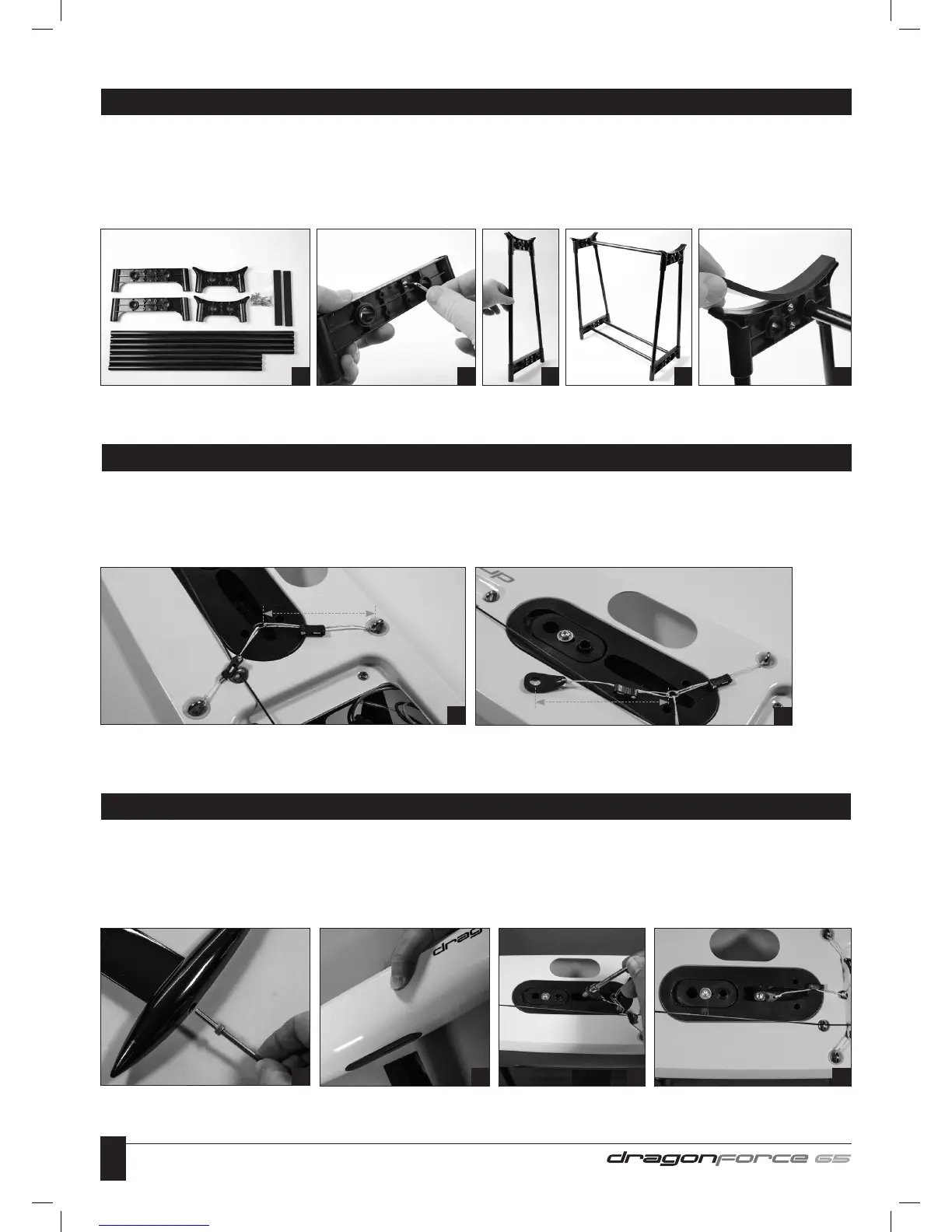
1 Identify all stand components from box. Note: The nuts, bolts and EVA foam support pads are located in the fittings pack.
2 Bolt the plastic moulded components together with the twelve nut & bolts supplied.
3 Construct the leg sections. Note: The leg sections are the four longer tubes.
4 Fit the three stretcher tubes.
5 Fix the soft EVA foam supports to the top surface of the stand to protect the Hull from scratches.
DISPLAY STAND ASSEMBLY
1 2 3 4 5
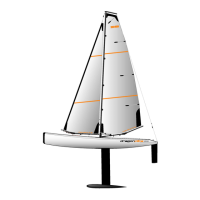
1 Adjust both sides of the Mainsheet Bridle so they are each 45mm from the Deck Eye to the ring.
2 From the fittings pack take out the Mainsheet Bridle Plate and a plastic Bowsie. Cut a 130mm length of Dyneema cord, tie one end
to the small hole in the Mainsheet Bridle Plate, pass the other end through the Bowsie (see opposite), through the ring and back to the
bowsie. Adjust to a length of 65mm, as shown in Photo 2 below, with the Bowsie positioned approximately half way along the length
and tie off at the bowsie. Trim off the spare end.
MAINSHEET BRIDLE
1
2
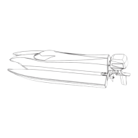
1 Identify all Keel & Bulb components from box. Note: The two, large fixing bolts are located in the fittings pack.
2 Use the longer bolt to fix the Keel Bulb to the Keel.
3 Slide the open end of the keel into the Keelbox slot in the underside of the Hull.
4 Thread the shorter bolt through the large hole in the Mainsheet Bridle Plate.
5 Secure the top fixing, being careful not to overtighten the bolt.
KEEL & KEEL BULB ASSEMBLY
2 3 4
45mm
65mm
5