5
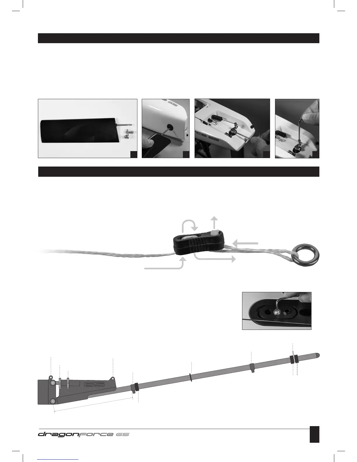
1 Identify all Rudder components from the box. Note: The metal Rudder Arm is located in the fittings pack.
2 Insert Rudder into Hull.
3 Ensure the Rudder is pushed fully up into the Hull, then, pushing the Rudder Arm down, tighten the grub screw. This will locate on the
flat section of the metal Rudder Shaft.
4 Slide the Steering Connector Rod through the top hole in the Rudder Arm. Set the Rudder Blade so that it’s in perfect fore/aft alignment
and tighten the top grub screw to locate the tiler arm onto the Steering Connector Rod.
Note: Rudder alignment will need to be checked and adjusted with the top grub screw when the boat is first powered up with the radio gear
switched on.
RUDDER ASSEMBLY
1 2 3 4
Note: Before you start building the rig it’s important that you read the three points below, they apply to the whole of the rigging procedure.
- To avoid the Dyneema cord fraying when cut, put a few drops of thin CA glue into the cord at the position of the cut then cut through the
glued cord at an angle. You will then have a hard, sharp point to the cut end that will be easy to thread through the Bowsies.
- After tying a knot and trimming off any spare cord, put a drop of thin CA glue on the knot to secure it. Extra time spent securing all knots
at this stage will ensure the long term reliability of the boat.
- Thread all Bowsies correctly as shown in the following diagram:-
MAINSAIL RIGGING
RIGGING PROCEDURE
If you follow all the dimensions stated in these rigging instructions, the boat will have a good, basic rig trim that will give it the sailing
characteristics and performance the designers intended.
1 Adjust the Sliding Deck Plate to align with the second graduation from the back as shown here.
Tighten the retaining bolt.
2 Set the position of the front Mainsheet Guide Eye on the Main Boom to the position shown below.
The positions of the silicone rings and sail clew hook are adjustable to facilitate correct sail trim.
1
2
3
4
5
Tie a substantial knot in the end of the cord, trim off any
surplus cord, apply a drop of CA glue to the knot and pull back
into the circular recess in the Bowsie.
80mm
Hole A
Locking Wheel
Vang Adjustment Wheel
Hole B
Mainsheet Guide Eye
Mainsheet Guide Eye
Rubber O Ring
Sail Clew Hook
Silicone Rings
Silicone Ring