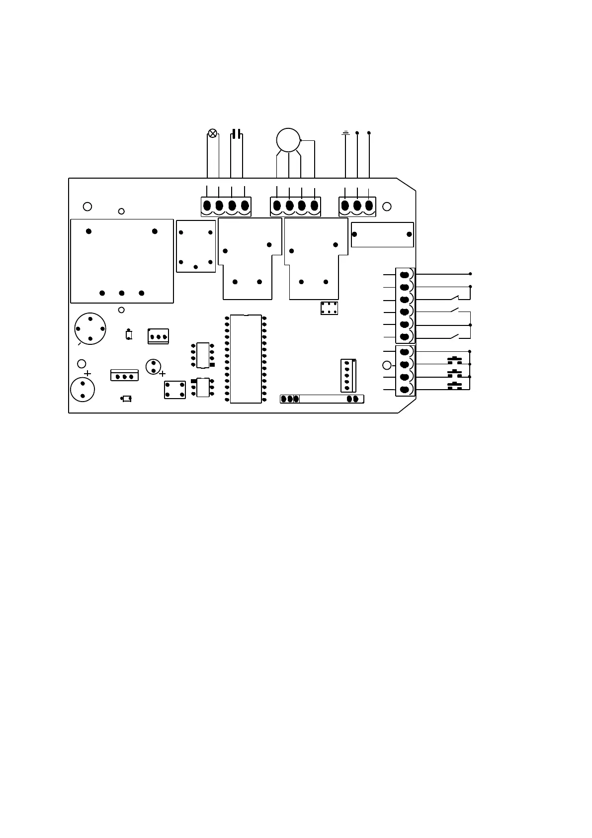
Figure 12
Wiring instruction:
1. Connect L and N to the power supply of AC220V/50HZ; AC110V/60HZ; L is live wire, N is
Neutral wire, PE is grounding wire.
2. Connect LAMP to D1, D2; voltage: AC220V/50HZ; AC110V/60HZ.
3. Connect the motor wire U to the REV motor wire, connect W to the FWD motor wire, and
connect V to the motor common wire.
4. Connect C, C to the capacitor wire.
X5 Terminal
24VDC Power supply for fittings +24VDC (Electric current ≤50mA);
GND Power ground;
I.R Photocell input (N.C.);
CLLM Close limit switch;
COM Limit switch common terminal;
OPLM Open limit switch.
X7 Terminal
COM Control button common terminal;
STP Stop control button (N.O.);
CLS Gate close control button (N.O.);
OPN Gate open control button (N.O.).