L
PEPE
1313
LAMPLAMP
PEPE
32
1
4
5
6
7
9
1010 1111
1212
8
MOTMOT
MOTMOT
COMCOM
MOT1MOT1
MOT2MOT2
CAPCAP
SPEEDSPEED GNDGND VCCVCC
N
L N
OFFOFF
ONON
X1X1
J5J5
U1U1
HALLHALL
J2J2
U2U2
S1S1
VR3VR3
VR4VR4
LEARNLEARN
POWERPOWER
J1J1
J6J6
J3J3
1313
1111
5 6
VR1VR1
VR2VR2
8
1010
SW1SW1
1 2
3
J4J4
12VDC12VDC
GNDGND
LimitLimit switchswitch
LoopLoop detetcordetetcor
O/S/CO/S/C switchswitch
ExternalExternal buttonbutton
PedestrianPedestrian switchswitch
M
PowerPower
EarthEarth
CapacitorCapacitor
LampLamp
InfraredInfrared sensorsensor
switchswitch
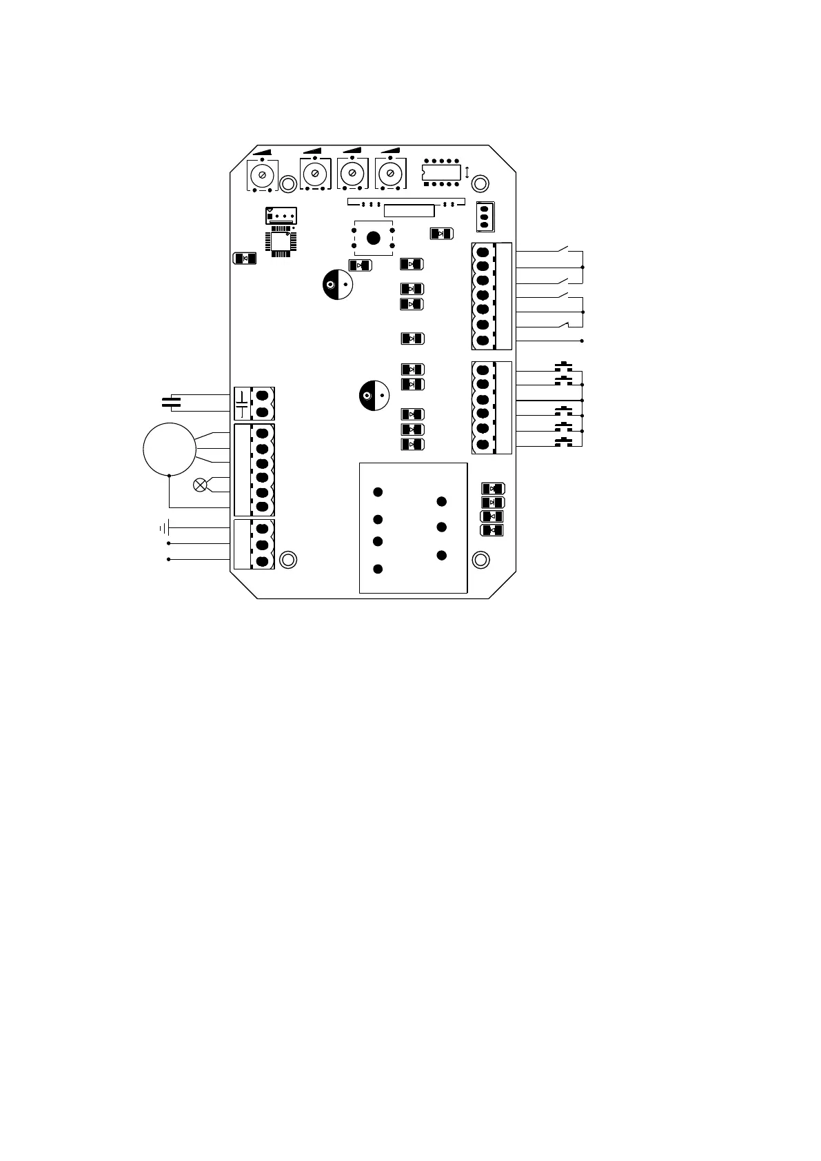
Figure 15
Wiring instruction:
1. Connect L and N to the power supply of AC220V/50HZ; AC110V/60HZ; L is live wire, N is
Neutral wire, and PE is grounding wire.
2. Connect LAMP to caution light; voltage: AC220V/50HZ; AC110V/60HZ.
3. Connect the motor wire MOT2 to the REV motor wire, connect MOT1 to the FWD motor wire,
and connect MOTCOM to the motor common wire.
4. Connect MOTCAP to the capacitor wire.
J2 (For the convenience of wiring, this terminal is accompanied with failure diagnosis light)
1. Gate close control button (N.O.)
2. Gate open control button (N.O.)
3. Stop control button (N.O.)
4. Control button common terminal
5. Open/Stop/Close/Stop loop control button (N.O.)
6. Pedestrian mode control button (N.O.)
J5 (For the convenience of wiring, this terminal is accompanied with failure diagnosis light)
7. Power supply for fittings: +12V(Electric current ≤100mA);
8. Photocell input (N.C.); short out the device if not used.
 Loading...