9. GND
10. Loop detector (sensor coil) connector (N.O.)
In the closing process, once vehicles are detected by the loop detector, the gate will open
soon; when the vehicle passes, the gate will close automatically. When the gate is in a
halted state, it will keep this state when vehicles are detected; after the vehicle passes, the
gate will close automatically.
In the above loop detector function, users can make the gate close automatically 12
seconds later after the vehicle passes. Change the No.4 key of the dip switch on circuit
board, and the gate will close automatically 12 seconds later after the vehicle passes.
11. Close limit switch
12. Limit switch and other input signal common terminal
13. Open limit switch
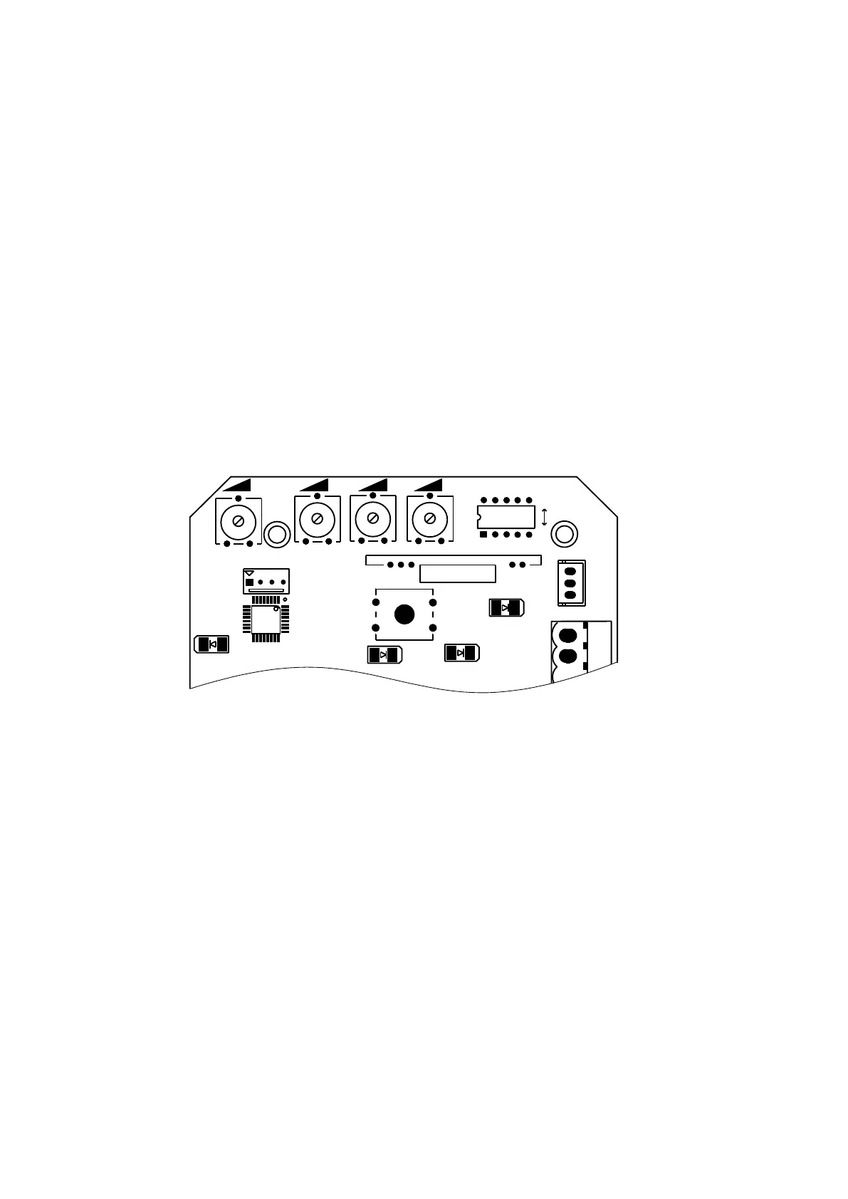
Function adjustment
Functional parameters of the control board equipped with microprocessor can be adjusted through
potentiometer and dip switch, so as to meet different installation requirements.
Figure 16
Adjusting knob
VR1: This knob is used for motor working total time adjustment.
Clockwise rotation to increase, counter-clockwise rotation to reduce. The total time can be set to 10
seconds as minimum and 90 seconds as maximum (DIP switch 5 at ON position).
VR2: For brake force adjustment in limit position.
Clockwise rotation to increase, counter-clockwise rotation to reduce.
Rotate to minimum to cancel brake function in place.
VR3: For slow stop width adjustment.
Clockwise rotation to increase, counter-clockwise rotation to reduce.
VR4: For motor output force adjustment to keep safe usage.
Clockwise rotation to increase, counter-clockwise rotation to reduce.
Note: the default setting is VR1, VR2, VR3, VR4 are the maximum value, and the user can adjust
according to the actual requirement.
Warning: the motor output force cannot set too large, just to be able to drive the gate.
 Loading...