2-8
2
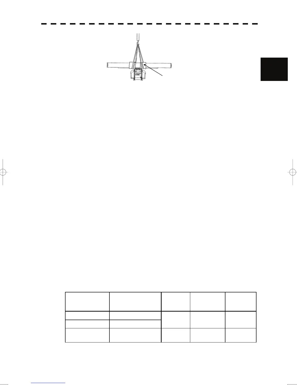
Fig.9 X-band
2) Installation procedures
a) Maintain a flat level surface on which to install the antenna.
• Use sufficiently thick steel material and reinforcement material for the antenna's
installation surface (mount base) to reduce vibration and impact. Keep the mount base
flat and smooth.
• If there is a partial gap between the mount base and the antenna chassis's legs, work on
the installation surface so that it becomes flat and smooth. If a gap exists and the
antenna is tightly clamped, the chassis will distort and become damaged by vibration.
b) Avoid using vibration-proof rubber and resin
• Do not insert an elastic body, such as vibration-proof rubber or resin, between the mount
base and the antenna chassis' legs. If rubber or resin is inserted, the amplitude of
vibration increases, resulting in the possibility of damage to the antenna. Furthermore,
if installation bolts become loose due to deterioration of rubber or resin, the antenna
may be damaged or fall from its mount.
3) Installation and clamping method
a) Installation direction
• Installation should be done so that the cable gland is oriented toward the stern.
b) Bolts, nuts and tightening torque to be used
• Use stainless steel bolts for the antenna and uniformly tighten all of the bolts using
double nuts for each bolt so that the antenna will not become loose (Table 2).
• Although the length of the bolt will differ according to the thickness of the mount base,
use a bolt long enough so that more than 4 millimeters of thread protrudes beyond the
double nuts after the double nuts have been tightened.
Table 2 Length of antenna mounting bolts and tightening torque
RADAR model Scanner Unit
Thickness of
Mount Base
(mm)
Bolt Torque (N-m)
JMA-5312-6/6HS NKE-2103-6/6HS
12
M10×55(mm)
SUS304
40
JMA-5322-7/9/6HS NKE-2254-7/9/6HS
JMA-5332-12 NKE-1130 19
M12×65(mm)
SUS304
65
Wrap a cloth
 Loading...


