EasyManua.ls Logo

JRC JMA-5312-6/6HS User Manual

JRC JMA-5312-6/6HS
160 pages
To Next Page IconTo Next Page
Page #1 background imageLoading...
Page #1 background image
INSTALLATIONINSTALLATION
MANUALMANUAL
MARINE RADARMARINE RADAR
EQUIPMENTEQUIPMENT
JMA-5312-6/6HSJMA-5312-6/6HS
JMA-5322-7/9/6HSJMA-5322-7/9/6HS
JMA-5332-12JMA-5332-12
01ETM ISO 9001, ISO 14001 Certified
Printed in Japan
Marine Service Department
+81-3-3492-1305
+81-3-3779-1420
tmsc@jrc.co.jp
Telephone :
Facsimile :
e-mail :
AMSTERDAM Branch
Telephone :
Facsimile :
e-mail :
+31-20-658-0750
+31-20-658-0755
service@jrceurope.com
SEATTLE Branch
Telephone :
Facsimile :
e-mail :
+1-206-654-5644
+1-206-654-7030
marineservice@jrcamerica.com
CODE No.7ZPRD0676CODE No.7ZPRD0676
JUL. 2013 Edition 7 JRCJUL. 2013 Edition 7 JRC
Not use the asbestos
For further information,contact:
URL http://www.jrc.co.jp

Table of Contents

Question and Answer IconNeed help?

Do you have a question about the JRC JMA-5312-6/6HS and is the answer not in the manual?

JRC JMA-5312-6/6HS Specifications

General IconGeneral
Frequency9410 MHz ±30 MHz
Output Power6 kW
Antenna Gain29 dB
Antenna Length6 feet
Display Size12.1 inches
Display TypeColor LCD
Antenna Rotation Speed24 rpm
Power Supply24 V DC
Operating Temperature-15°C to +55°C
TypeX-Band Radar
Range Scales0.25, 0.5, 0.75, 1.5, 3, 6, 12, 24, 48 NM
Beam Width1.9° horizontal

Summary

Installation of the Scanner

Installation Procedure

Step-by-step instructions for scanner installation, including hoisting.

Connecting the Installation Cable NKE-2103

Details for connecting scanner cable model NKE-2103 (JMA-5312-6/6HS).

Connecting the Installation Cable NKE-2254

Details for connecting scanner cable model NKE-2254 (JMA-5322-7/9/6HS).

Connecting the Installation Cable NKE-1130

Details for connecting scanner cable model NKE-1130 (JMA-5332-12).

Installation of the Display Unit

Selecting the Installation Position

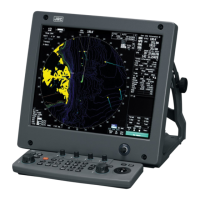
Guidelines for choosing the best location for the display unit.

Initial Setting

How to Open the Serviceman Menu

Procedure to access the serviceman configuration menu.

Tune Adjustment

Adjusting transmitter/receiver tuning for optimal performance.

Bearing Adjustment

Calibrating radar bearing display to match ship's compass.

Measures Against Noise Interference in the Radio Equipment

Shield of Devices

Procedures for shielding components to prevent noise emission.

Related product manuals