3.6 CONNECTING TO THE GPS RECEIVER
1) When using JRC's GPS receiver
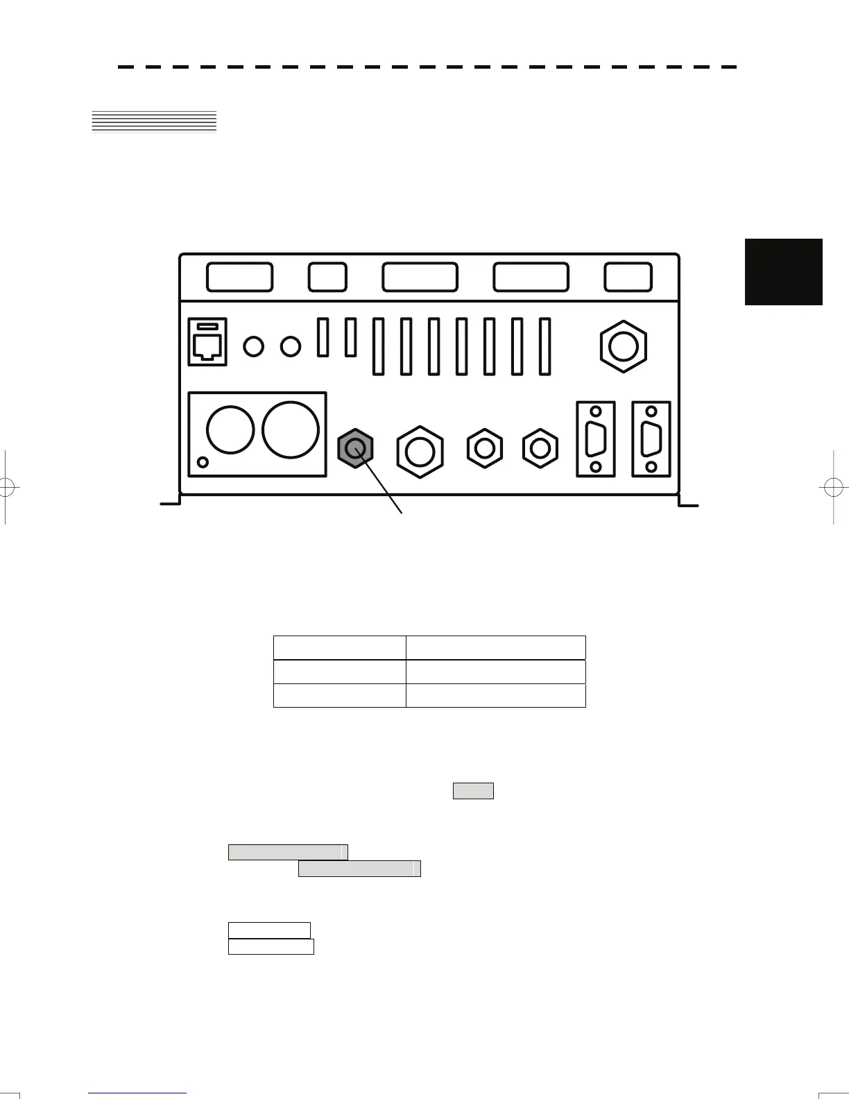
When using JRC's GPS receiver, such as GPS124/DGPS212, directly connect the GPS receiver
t
o the
connector for which "GPS" is engraved at the rear of the radar process unit cabinet. Turn the plug
attached to the connector until it cannot be turned any further.
3
The JRC’s GPS receiver is connected here.
F2 F3
POWER SCANNER
KEY BOARDGPS
GYRO
COMPASS
VIDEO
DC OUT
VIDEO NMEA
AUX
E
J2J1
J7
J6J5
J4
J3
J8
2) When using other maker's GPS receiver or a
n NMEA data output device
When receiving NMEA data from JRC's NMEA data out
put device other than ones mentioned above or
other maker's GPS receiver, remove the radar process unit cabinet cover, and connect the signal line to the
terminals located on the terminal board as shown in the following table:
JMA-5300MK2 side GPS receiver side
TB4303 GPSRXD- Data return
TB4303 GPSRXD+ Data output from the receiver
3) Set the GPS communication port as shown following procedure.
1) P
ress and hold [RADAR MENU] key.
Th
e Code Input menu will appear.
2) Press the [0] key, and put the cursor on the ENT button, and press the [ENT] key.
The Serviceman Menu will appear.
3) Open
the COM Port Setting menu by performing the following menu operation.
2. Installation Menu
→ 5. COM Port Setting
4) Press the [5] key.
Un
its of Select NAV Equipment are switched.
Internal GPS : The receive port
is selected GPS
connector of processor unit (JRC’s GPS).
External GPS : The receive port is selected GPS terminal of terminal board circuit.
3-8
 Loading...


