• Rotation signal
Connect the rotation signal line to the following terminals located on the terminal board:
TB4302-BPO
TB4302-BPOE (return)
Connect the rotation reference signal line to the following
t
erminals located on the terminal board:
TB4302-BZO
TB4302-BZOE (return)
Pull up both lines to 5 V at 1 kilo-ohm before using them.
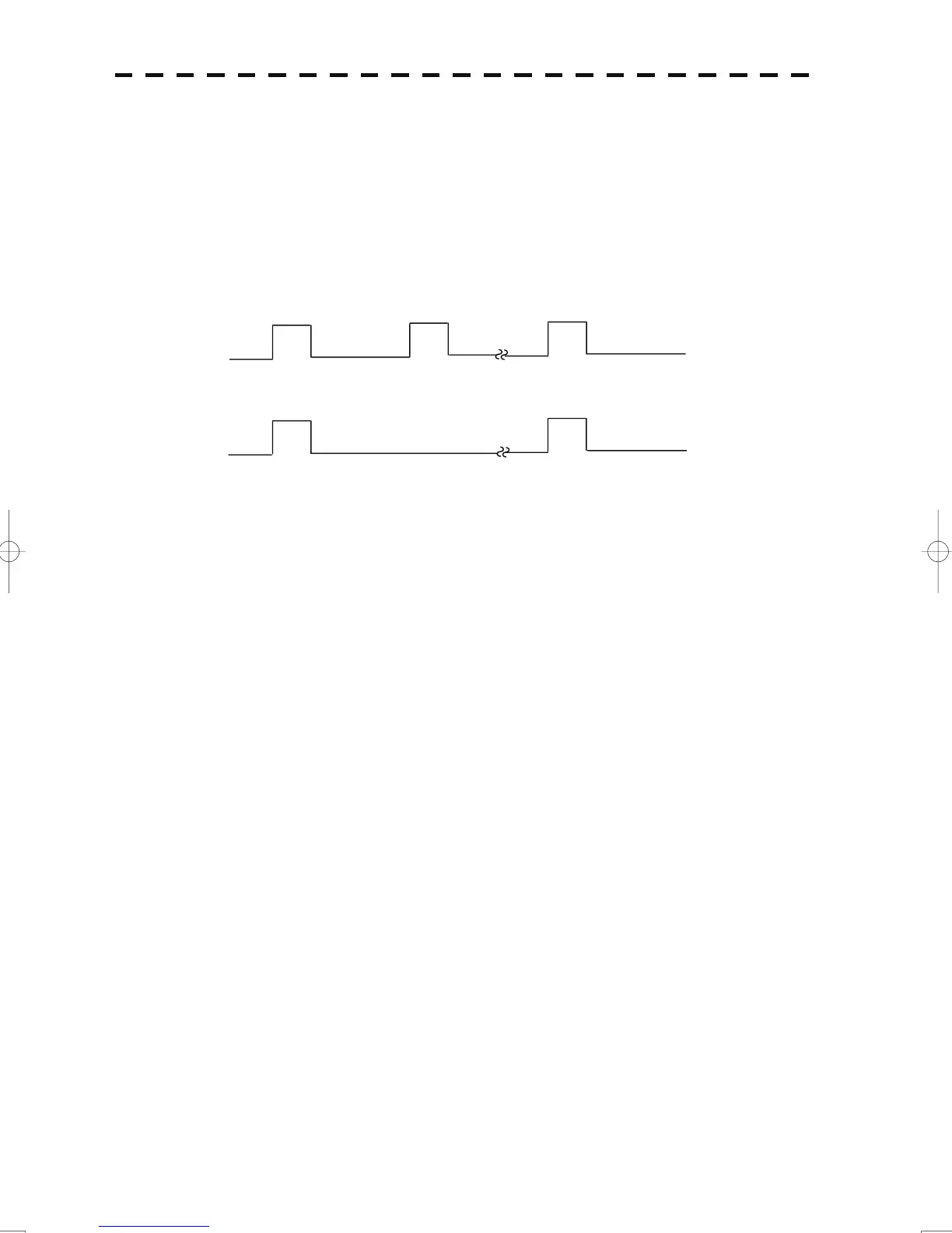
BP
2048 pulses per
c
cle
BZ
1 pulse per cycle
The radar JMA-5300MK2 can output only a one-phase rotation signal.
When a sub display unit needs a two-phase rotation signal, the one-phase input should be normally set
to logic "H" or "L".
2)
Radar buoy
• V
ideo signal
Co
nnect the radar buoy video signal line (50 ohm termination) to the terminal located on the terminal
board as follows:
TB4302-RBVD
TB4302-RBVDE
3) When used as a slave display unit
The slave input includes the following signals:
Video input (50 ohm termination)
Trigger signal input (1 kilo-ohm termination: TTL input)
Rotation signal
• V
ideo signal
Co
nnect the video signal input line to the terminal located on the terminal board as follows:
TB4310-VD
TB4310-VDE
• Tr
igger signal
Co
nnect the trigger signal input line to the terminal located on the terminal board as follows:
TB4310-TRG
TB4310-TRGE
3-23
 Loading...


