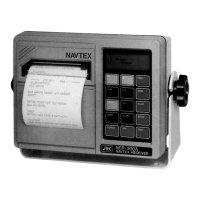
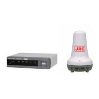
The JRC NAVTEX Receiver, Model NCR-330, is a sophisticated device designed to comply with IMO performance standards for narrow-band direct printing telegraph equipment. Its primary function is to receive navigational and meteorological warnings, as well as urgent information, for ships. The system comprises a Receiver (CMN-2330) and a Main Processor (CDJ-2330).
Function Description
The NCR-330 operates by receiving signals at 518kHz ± 85Hz from an antenna terminal. These signals are converted into a baseband signal by the CMN-2330 Receiver and then output to the CDJ-2330 Main Processor. The CDJ-2330 processes these signals by bit-synchronizing and frame-synchronizing them, editing them according to ITU-R. 476-5, 540-2, and 625-3(B) procedures. The edited messages are then sent to a thermal printer for output. Control signals generated by the control panel are input to the CDJ-2330 Main Processor, which in turn controls the various functions of the equipment.
The CMN-2330 Receiver is composed of three main sections: a power supply section, a receiver section, and an input/output section. The power supply section handles the device's power requirements, converting input voltage to the necessary operating voltages for the internal circuits. The receiver section is responsible for processing the incoming radio signals. The input/output section manages the communication between the receiver and other components or external systems.
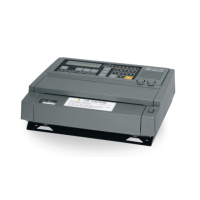
The CDJ-2330 Main Processor also has three sections: a demodulator section, a CPU section, and a printer section. The demodulator section converts the received signals into digital data. The CPU section, acting as the brain of the system, processes this data, manages user input, and controls the overall operation. The printer section is responsible for printing the received messages and system status.
Important Technical Specifications
CMN-2330 Receiver:
- Power Supply Section:
- Input voltage: DC 10.8V~35V
- Output voltage: +5V, +9V
- Receiver Section:
- Input frequency: 518kHz
- Input impedance: 50Ω (High-impedance)
- Output frequency: 1,700Hz ± 85Hz
- Output level: 0dBm (600Ω, UNBAL.)
- Input/Output Section:
- RS-422A interface
- Current circuit
- External alarm signals
CDJ-2330 Main Processor:
- CPU Section:
- CPU (Central Processing Unit)
- Oscillator
- ROM (Read Only Memory): 64kB
- RAM (Random Access Memory): 32kB
- EEPROM (Electrically Erasable Programmable Read Only Memory)
- PLD (Programmable Logic Device)
- Driver
Usage Features
The control panel provides several features for operating the device:
- Power Management:
- Power lamp (1): A green lamp indicates that the power is on.
- Power on (Normal): Press and hold the POWER switch for at least two seconds.
- Power on (Initialize): While holding down the TEST switch, press the POWER switch.
- Power off: Press and hold the POWER switch for at least two seconds.
- Message Reception & Status:
- Receive lamp (3): Illuminates during signal detection and blinks during message text reception.
- Paper lamp (6): An orange lamp that blinks to indicate a shortage of paper.
- Alarm lamp (8): A red lamp that blinks when an alert message is received.
- Control & Navigation:
- Self-diagnostic Test (4): Initiated by pressing the TEST switch.
- Setting of Illumination (5): Adjusted by pressing the DIMMER switch.
- Feed the paper (7): Activated by pressing the FEED switch.
- Stop the Alarm (9): Press the ALARM OFF switch.
- Menu start / end (10): Press the MENU switch.
- Enable (11): Press the ENT switch.
- Disable (12): Press the CLR switch.
- Confirmation of Programmed Status (13): Press the STATE switch.
- Change the symbol (14): Use the ▲, ▼ switches.
- Alphabet (15): Indicates the selected letter (B1 or B2).
- Symbol Alphabet (16): The lamp at the bottom right of the display indicates if the selected letter is enabled (ON) or disabled (OFF).
Function Setting:
The equipment allows users to select a receiving coast station, message type, and receiver status.
- State start: Press MENU to initiate "STATE PROGRAM START."
- Select station:
- Press ENT to "SET COAST STATION?"
- Use ▲ for ascending order, ▼ for descending order.
- Press ENT to enable (bottom right lamp turns on), CLR to disable (bottom right lamp turns off).
- Press MENU to detect disabled areas.
- Press CLR for "SET COAST STATION?" if no station is set.
- Select message:
- Press ENT to "SET MESSAGE TYPE?"
- Use ▲ for ascending order, ▼ for descending order.
- Press ENT to enable (bottom right lamp turns on), CLR to disable (bottom right lamp turns off).
- Press MENU to detect disabled message types.
- Press CLR for "SET MESSAGE TYPE?" if no message type is set.
- Select state:
- Press ENT to "SET STATE?"
- Alarm: Press ENT/CLR for "ALARM SOUND ON? ON/OFF." (ON: ENT, OFF: CLR)
- Character size: Press ENT/CLR for "CHARACTER SIZE LARGE? Large / Normal." (L: ENT, N: CLR)
- Press CLR for "SET STATE? STATE END" if no state is set.
- State end: Press MENU for "STATE END."
Maintenance Features
- Self-diagnostic Test: The device includes a self-diagnostic test function (activated by pressing the TEST switch) to check the receiving circuit. During this test, the break-in (BK) relay is turned ON to shut off external input, protecting the receiver from excessive input induced on the antenna. This circuit consists of a photocoupler (PHT1) and a transistor (TR3), capable of receiving 12V ~ 24V at the BK terminals (TB-6,7).
- Power Supply Protection: The power supply section incorporates fuses (F1, F2) to protect against overcurrent. If the polarity of the power supply is incorrect, current flows through CD8 and F1, causing F1 to blow, thus preventing damage.
- Data Preservation: The RAM (IC7) in the CPU section, which stores receiving data and provides a work area, is backed up by a battery for more than 24 hours after power-off, ensuring that necessary data, including information from the switch, is preserved.
- Error Indication: The paper lamp (orange) blinks to indicate a paper shortage, and the alarm lamp (red) blinks when an alert message is received, prompting user intervention for maintenance or acknowledgment.