Do you have a question about the JRC JAX-9B and is the answer not in the manual?
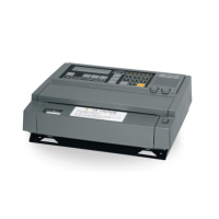
Describes the primary purpose and capabilities of the JAX-9B weather facsimile receiver.
Details the various operational modes, recording capabilities, and advanced features of the JAX-9B.
Explains the automatic selection of frequencies based on receiving conditions for optimal performance.
Details the internal clock feature used for program timing and time indication.
Describes how the internal clock can be automatically corrected using a GPS receiver.
Explains the optional function to display received images on a personal computer.
Covers the support for a Remote Maintenance System, allowing remote monitoring and management.
Lists the standard and optional components included with the JAX-9B weather facsimile receiver.
Provides a list of spare parts for the JAX-9B, including item numbers, descriptions, and quantity.
Illustrates the interconnection of the JAX-9B with various optional components and external systems.
Details the different circuit boards used within the JAX-9B equipment and their respective models.
Presents a functional block diagram showing the internal components and their interconnections within the JAX-9B.
Defines key terms and concepts related to facsimile broadcasting and the operation of the JAX-9B.
Lists detailed technical specifications for the JAX-9B facsimile receiver, including functional abilities.
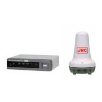
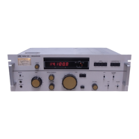
Details the specifications of the synthesized receiver component of the JAX-9B.
Outlines the general physical and electrical specifications of the JAX-9B unit.
Specifies the environmental operating conditions for the JAX-9B, including temperature ranges.
Provides specifications for the optional Rectifier Unit used to power the JAX-9B.
Specifies the required clearance around the JAX-9B for proper ventilation and maintenance access.
Provides step-by-step instructions for physically installing the JAX-9B unit.
Details the mounting procedure for the optional Rectifier Unit.
Highlights important safety and operational precautions to be observed during installation.
Provides instructions for installing the whip antenna, including mounting the post and junction box.
Explains how to connect cables to the junction box for the whip antenna installation.
Details the sealing and grounding procedures for antenna connections to ensure proper functionality and safety.
Describes the setup process for displaying received facsimile images on a personal computer using optional kits.
Provides instructions for installing the Communication I/F unit, which converts serial data for PC connection.
Outlines the steps for connecting the JAX-9B to a Remote Maintenance System.
Details the procedure for installing the PC interface kit into the JAX-9B unit.
Presents a detailed table outlining the wiring connections for power, external receivers, GPS, and PC interface.
Illustrates the standard wiring configurations for power supply and signal connections.
Details the specific wiring required for connecting the JAX-9B to a PC for displaying received images.
Shows the wiring connections for establishing a link with the Remote Maintenance System.
Lists the types of cables used for various connections, including AC power, DC power, antenna, and data signals.
Provides a visual guide to the standard wiring configuration for the JAX-9B.
Explains the wiring procedures for connecting the JAX-9B to an AC power supply using the optional rectifier unit.
Details the process of connecting the JAX-9B to a personal computer for data transfer and image display.
Illustrates the wiring diagram for connecting the JAX-9B to a Remote Maintenance server.
Provides step-by-step instructions for assembling and connecting the antenna connector.
Explains the correct method for connecting cables to the terminal blocks of the JAX-9B.
Details the specific procedure for connecting cables to the DC power source terminal block.
Describes the connection method for external interface signal terminals.
Outlines the connection interface and procedure for integrating a decoder from Kyodo News Service.
Covers the initial settings required for the JAX-9B upon installation, including clock and frequency registration.
Details the procedure for setting the internal clock of the JAX-9B, including automatic correction.
Explains how to register and confirm frequency channels, either via software or the unit's panel.
Describes the process of registering timer programs for automated operations using software or the unit's panel.
Provides instructions for switching the display language of the JAX-9B to Japanese, including applying labels and changing LCD settings.
Details how to connect a GPS receiver for automatic time correction and its interface specifications.
Explains how a connected GPS receiver automatically corrects the internal clock for accurate timekeeping.
Notes that automatic time correction requires only connecting the GPS receiver and no specific setup on the JAX-9B.
Lists the interface specifications for connecting a GPS receiver to the JAX-9B.
Emphasizes the importance of manually setting the internal clock once after connecting a GPS receiver.
Outlines how to check the automatic time correction operation and confirm its successful execution via the LCD.
Guides the user through installing the necessary device driver for the RS-422/USB converter.
Details the steps to install the RS-422/USB converter driver using the Windows "Found New Hardware" wizard.
Provides instructions for installing the FAX image receiving software and configuring the PC connection.
Lists the checks for verifying the standard operational status of the JAX-9B after installation.
Describes how to check the function of displaying received FAX images on a PC.
Provides outline drawings and dimensions for the main JAX-9B unit.
Shows the outline drawings and dimensions for the optional Rectifier Unit NBA-5143.
Presents outline drawings and dimensions for the 6m Whip antenna NAW-60.
Displays outline drawings and dimensions for the Junction box JQD-69C.
Provides outline drawings and dimensions for the RS-422/USB Converter 7ZZNA4017.
| Type | Communications Receiver |
|---|---|
| Sensitivity | 1 μV (10 dB S/N) |
| Frequency | HF |
| Display | Digital |
| Mode | AM, SSB, CW |