3. Wiring
JAX-9B W-FAX Installation Manual
23
7ZPNA4096
3. Wiring
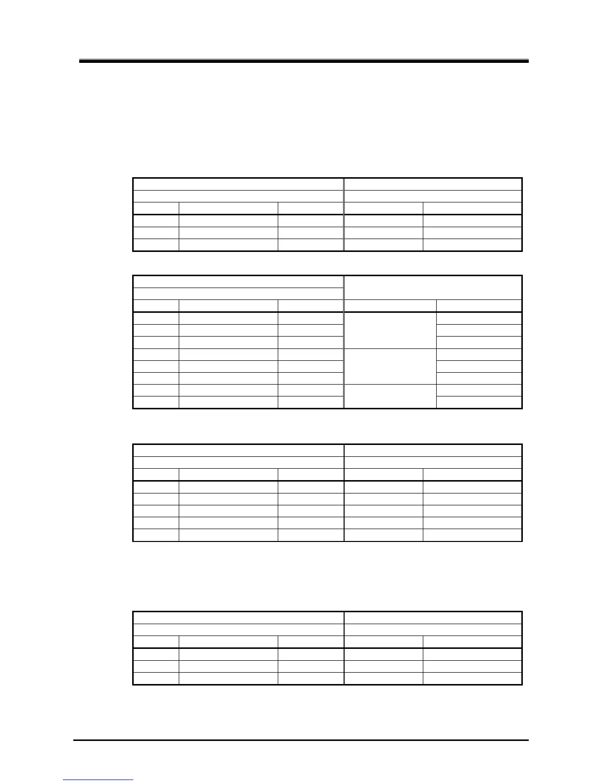
3.1. Wiring table
3.1.1. Standard wiring
1) Power source
JAX-9B Rectifier Unit
Terminal: TB101
Terminal on the Panel of PSU
PIN No. Signal Color of cable PIN No. Signal name (Printing)
1 DC+ Red - DC24V OUT (+)
2 DC- Blue - DC24V OUT (-)
3 Earth Green - FG
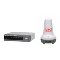
2) BK, External receiver, GPS
JAX-9B
Terminal: TB102
Connected Equipment
PIN No. Signal Color of cable Equipment Signal
1 AF Signal (GND) - AF OUT(-)
2 AF Signal (+) - AF OUT(+)
3 Shield -
MF/HF Receiver
Shield
4 BK Signal (-) - BK OUT(-)
5 BK Signal (+) - BK OUT(+)
6 Shield -
MF/HF transmitter
Shield
7 GPS Data (-) - NMEA OUT(-)
8 GPS Data (+) -
GPS receiver
NMEAOUT(+)
3.1.2. Display received image on PC
JAX-9B RS-422 / USB Converter
Terminal: TB103
Terminal
PIN No. Signal Color of cable PIN No. Signal
2 Shield - - -
3 PC TX (-) - 4 NC/RX-
4 PC TX (+) - 3 NC/RX+
5 PC RX (-) - 2 D-/TX-
6 PC RX (+) - 1 D+/TX+
* ”Welcome to the Found New Hardware wizard” will appear after connecting the converter
to JAX-9B. Refer to the clause 5.2.
3.1.3. Remote Maintenance System
JAX-9B VDR: JCY-1800
Terminal: TB103
NMEA input terminal
PIN No. Signal Color of cable PIN No. Signal
7 Shield - - -
8 RMS OUT (-) - - RX (-)
9 RMS OUT (+) - - RX (+)