2. Installation
JAX-9B W-FAX Installation Manual
21
7ZPNA4096
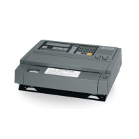
2.9. Putting the PC interface kit in JAX-9B
Put the cable with a connector and terminal in JAX-9B.
1) Turn off the circuit breaker of the electricity distribution board, to which JAX-9B is connected.
Separate the terminal (TB101) of JAX-9B and cut the power source.
2) Remove JAX-9B from the mount base. Refer to the clause 2.2.
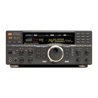
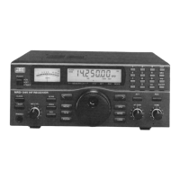
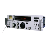
3) Unscrew the four screws for fixing the cover to the main frame. Remove the cover from JAX-9B.
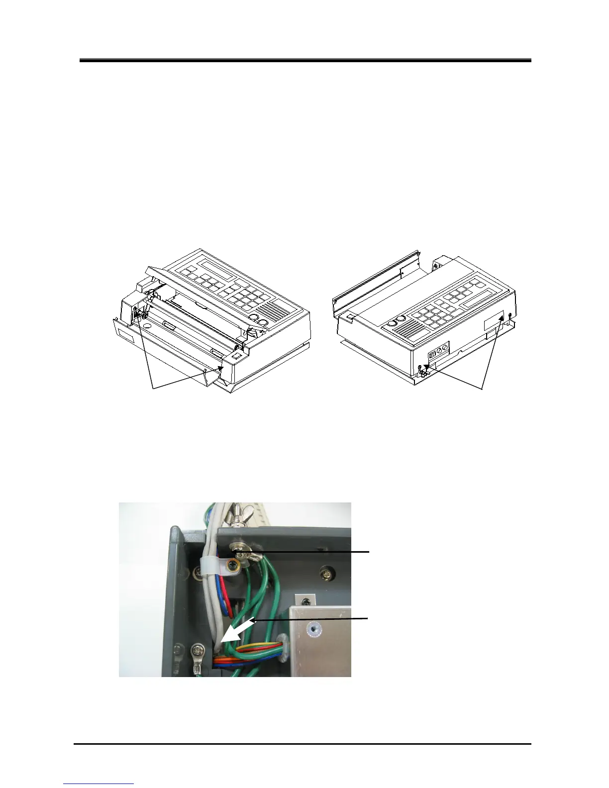
4) A speaker and two volumes are fixed on the cover. Disconnect the cable with speaker and volumes from
J501 connector on the control board.
5) Turn JAX-9B over and remove the cable clamp for power cable.
Insert the connector side of 7ZCNA4076 from the bottom of JAX-9B.
Unscrew and remove the cable clamp.
Put the cable through the square hole.
(Bottom)
 Loading...