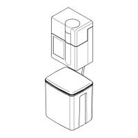
JUDO QUICKSOFT-UNO 11
Installation
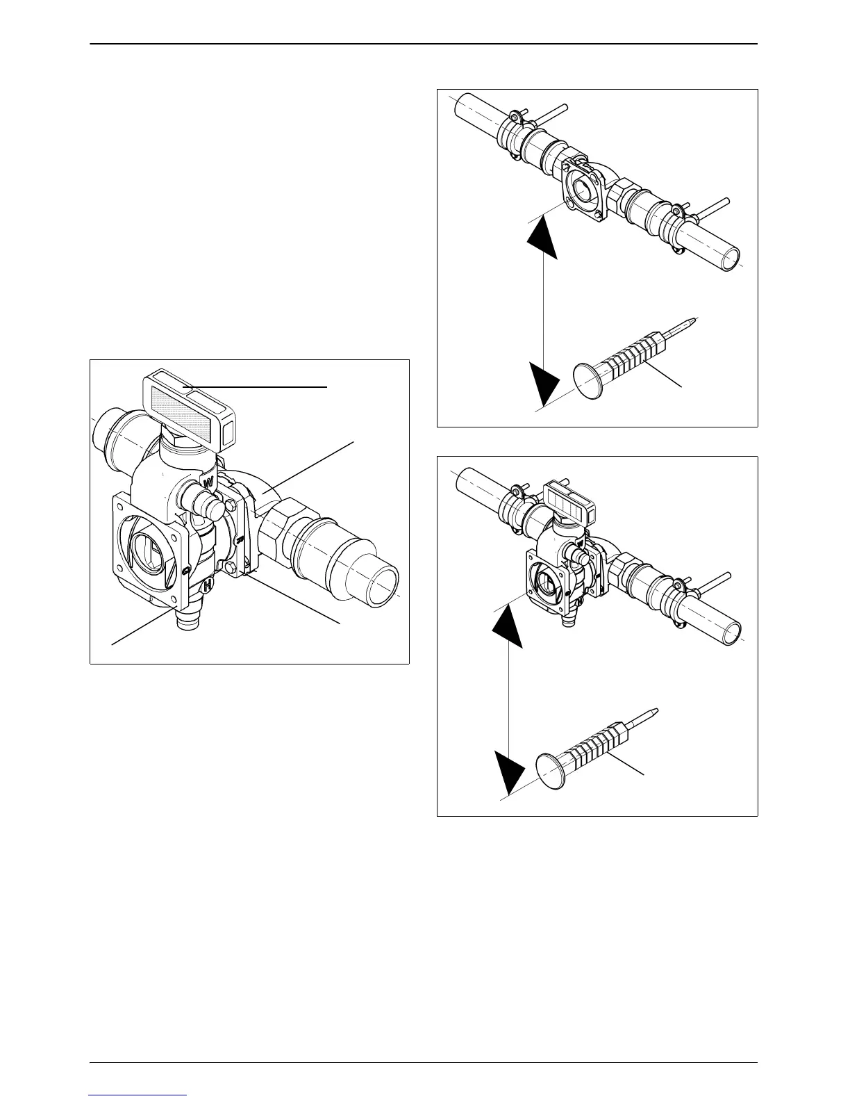
4.1.5 Assembly of the bypass valve
(accessories)
The flange (c) of the bypass valve marked
with the cast in letter “R” (pipe) is screwed
onto the built-in rotary flange (b). The Sof-
tener is fitted onto the flange (d) marked with
the cast in letter “G” (unit). The hand lever
(a) of the bypass valve can be positioned
anywhere above the unit or to the side if
there is a large space between the pipe and
wall. The installation should be carried out,
depending on the local circumstances, so
that the hand lever (a) is easily accessible
(see Fig. 5), Fig. 6) and Fig. 7)).
a Hand lever
b Built-in rotary flange
c „R“ pipe flange
d „G“ unit flange
e Wall support
4.1.6 Fitting the wall support
For further information, please refer to the
installation instructions for the wall support.
Fig. 5: bypass valve
a
b
c
d
Fig. 6:
Wall support without bypass valve
Fig. 7: Wall support with bypass valve
300
e
300
e