Wiring
1. Fully disconnect your gate opener and its control box from their power source.
2. Access the gate opener circuit board.
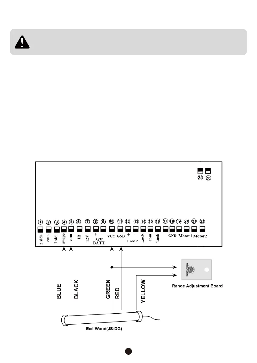
3. Separate the different-colored wires coming from the range adjustment board and from
the end of the wand’s cord.
4. The yellow wires provide the range adjustment signals. Connect the ends of the two
yellow wires together, wrapping the connection in electrical tape or covering it with a
wire nut.
4
Only make connections and adjustments to your gate opener and its circuit
board in accordance with their separate manual(s). Never leave any wiring
exposed.
5. The blue wire provides the main control signals. Connect it to the pin on the circuit
board that controls only opening the gate. This varies between systems but is usually
marked “OPEN”, “EXIT”, “BLU”, or “SWIPE”. For most circuit boards, you will need to
loosen the bolt limiting access to each pin, insert the wire up to its insulation, and then
tighten the holding bolt back down. Use the diagrams below if they fit your model.