Testing
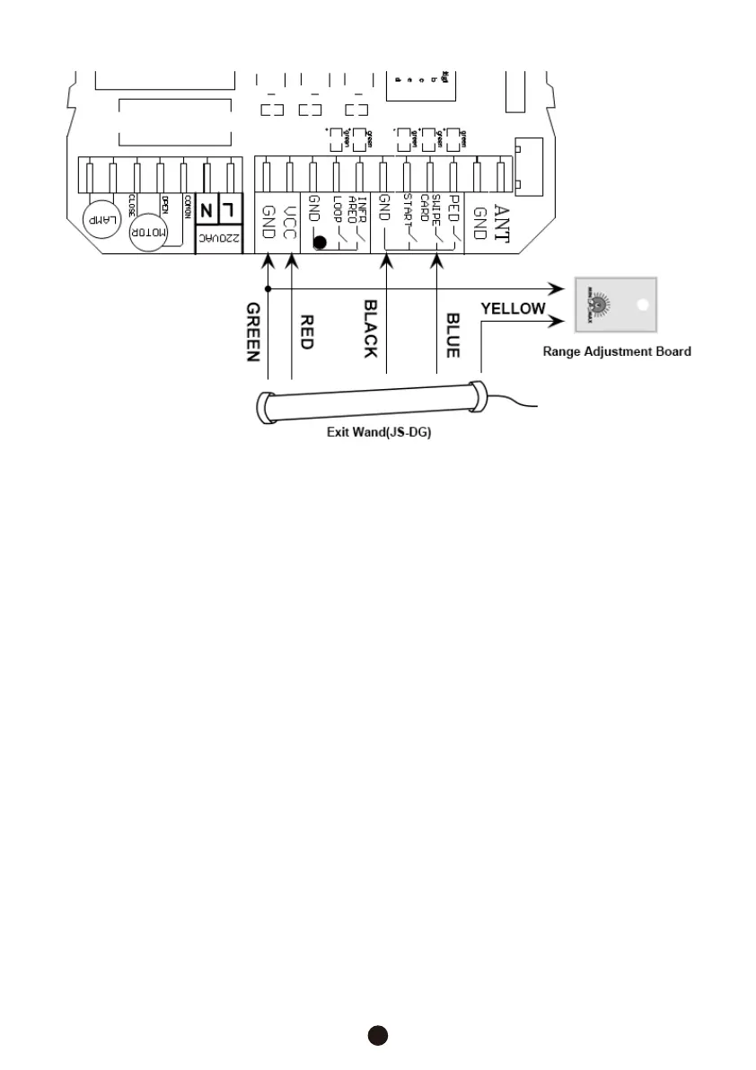
6. The black wire is the return line for this electrical signal. Connect it to the nearby
return pin on the circuit board, usually marked “COM”, “COMMON”, “GND”, or “GRN”,
in the same way.
9. Find a suitable place within or near the gate opener circuit board for the range
adjustment board to go.
7. The green wire from the exit wand is the negative or return power connection.
Connect it in the same way to the matching negative pin on the circuit board or to
one of the various return pins. These may be marked “-12V”, “-24V”, “AUX V-“,
“AUX OUT L”, “COM”, “COMMON”, “GND”, or “GRN”.
8. The red wire is the positive or live power connection. Connect it in the same way to
the positive pin on the circuit board that provides suitable voltage to external devices.
Again, this varies between systems but it may be marked “+12V”, “+24V”, “VCC”,
“AUX V+”, “AUX OUT H”, or “LOCK+”. For circuit boards providing AC power, the red
and green wire can be connected to the live and return pins in either order.
The green wire from the range adjustment board is also a return line. Connect it to any
similar pin in the same way.
5
1. Remove any vehicle or large potentially moving metal object from the area around the
exit wand.
2. Reconnect the gate opener and its control box to their power source. Wait at least
60 seconds while the system calibrates.
 Loading...