− 74 −
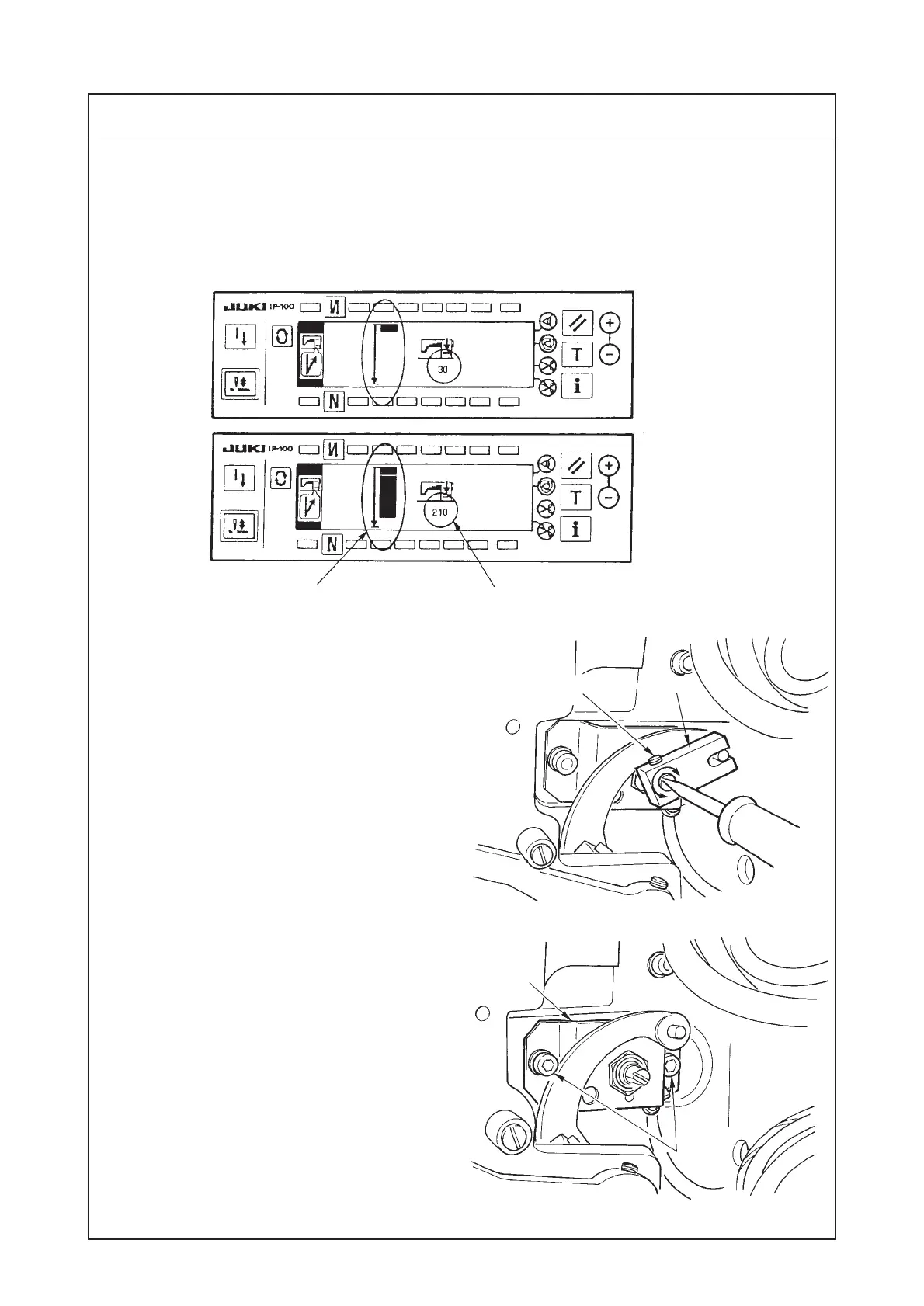
10) When reverse feed control lever !0 is turned on in the reverse feed control lever adjustment screen,
the numeric value on the panel changes.
When the numeric value is not within the range of 22 to 32 (standard assembling value) with reverse
feed control lever !0 lifted (off), re-adjust as described in 11) and after.
Procedures of disassembling/assembling
Level meter changes.
!5
!6
Numeric value changes.
off
on
11) Adjusting the reverse feed control lever sensor
Loosen setscrew !2 in the variable resistor link.
Turn the feed lever sensor shaft and adjust
the numeric value of the reverse feed control
lever adjustment screen to 22 to 32 (standard
assembling value) using a flat-blade
screwdriver.
After the adjustment, tighten setscrew !2 in the
variable resistor link.
12) Replacing the reverse feed control lever
sensor
Loosen setscrew !2 in the variable resistor link
and remove variable resistor link !3.
Rmove two setscrews !5 in the feed lever
sensor installing plate and remove feed lever
sensor installing plate !6.
* Replace the sensor with a new feed lever sensor
(Part No. : HD001530000).
After the replacement, perform 11) Adjusting
the reverse feed control lever sensor.
(Caution) It is not possible to move to the other
screen from the reverse feed control
lever adjustment screen. When the
adjustment is completed, turn off
the power.
Reverse feed control lever adjustment screen
!2
!3
 Loading...