EasyManua.ls Logo

JUKI IP-110 Type F User Manual

JUKI IP-110 Type F
42 pages
To Next Page IconTo Next Page
Page #1 background imageLoading...
Page #1 background image
i
ENGLISH
* "CompactFlash(TM)" is the registered trademark of SanDisk Corporation, U.S.A.
IP-110 TYPE F
INSTRUCTION MANUAL
Question and Answer IconNeed help?

Do you have a question about the JUKI IP-110 Type F and is the answer not in the manual?

JUKI IP-110 Type F Specifications

General IconGeneral
ModelIP-110 Type F
Stitch TypeLockstitch
Sewing Speed1, 500 rpm
Needle TypeDPx5
Air Pressure0.49MPa

Summary

1. INSTALLING THE OPERATION PANEL

2. CONNECTING THE CORD

3. MACHINE HEAD SETTINGS

4. ADJUSTING THE MACHINE HEAD ANGLE

5. EXPLANATION OF THE OPERATION PANEL

5-1. Names and functions of each components

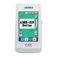
Identifies and explains the purpose of each switch and component on the operation panel.

5-2. Adjusting the contrast of the operation panel screen

Details how to adjust the screen brightness and contrast settings.

5-3. Connection of the production support switch

Explains how to connect the optional production support switch.

5-4. Basic screen

Introduces the initial screens displayed after turning on the operation panel.

Reverse stitching pattern operation

Guides the user on how to set and use the reverse stitching pattern.

Overlapped stitching pattern operation

Explains the procedure for setting and using the overlapped stitching pattern.

Programmed stitching pattern operation

Details how to program and use various operation steps for programmed stitching.

Cycle sewing pattern operation

Describes how to set and sew multiple patterns in a cycle.

6. BOBBIN COUNTER

7. NO. OF PCS. COUNTER

8. RE-SEWING SWITCH

9. NEEDLE UP/DOWN COMPENSATION SWITCH

10. ON/OFF SWITCH OF THE MATERIAL EDGE SENSOR

11. AUTOMATIC THREAD TRIMMING SWITCH

12. ONE-SHOT AUTOMATIC STITCHING SWITCH

13. THREAD TRIMMING PROHIBITION SWITCH

14. SIMPLIFIED FUNCTION SETTING

15. KEY-LOCK FUNCTION SETTING

16. FUNCTION SETTING

17. OPTIONAL INPUT/OUTPUT SETTINGS

18. AUTOMATIC COMPENSATION OF NEUTRAL POINT OF THE PEDAL SENSOR

19. INITIALIZATION OF THE SETTING DATA

20. INFORMATION

Maintenance management function

Details the settings and displays for maintenance tracking.

Working measurement function

Explains how to use the working measurement functions for factor, speed, and time.

Date and time setting

Describes how to set the current date and time on the operation panel.

21. EXTERNAL INTERFACE

22. ERROR DISPLAY

22-1. Error code list (Error display in panel)

Lists and explains various error codes that may appear on the panel.
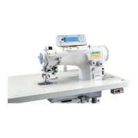
Related product manuals