4. PROCEDURES OF DISASSEMBING/ASSEMBLING AND CAUTIONS .................... 52
(1) Adjusting and assembling of the gear box (large) .............................................................................. 52
(2) Replacing the motor ........................................................................................................................... 54
(3) Replacing the timing belt .................................................................................................................... 56
(4) Removing/installing the gear box cover.............................................................................................. 58
(5) Disassembling/assembling the needle bar support base shaft (asm.) ............................................... 58
(6) Adjusting/assembling the reverse feed control lever (A-SR only) ...................................................... 70
5. MAINTENANCE............................................................................................................ 76
(1) Changing procedure between single phase 100 to 120V and 3-phase 200 to 240V ......................... 76
(2) Replacing procedure of the printed circuit board ................................................................................ 77
(3) Maintenance of the hook lubricating pipe oil filter............................................................................... 78
(4) Cleaning the cooling fan ..................................................................................................................... 79
(5) Applying the exclusive grease ............................................................................................................ 80
(6) Hook shaft gear .................................................................................................................................. 84
(7) Adjusting the needle rocking link ........................................................................................................ 85
(8) Lubricating to face plate section (A-SS and A-SU, A-SR only) .......................................................... 86
(9) Protruding amount of the hook shaft .................................................................................................. 88
(10) Adjusting the feed stepping motor unit (A-SR only).......................................................................... 88
(11) Draining of CB type .......................................................................................................................... 89
(12) Cleaning the dust bag of CB type..................................................................................................... 89
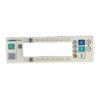
6. OPERATION PANEL.................................................................................................... 90
(1) Names of the respective sections....................................................................................................... 90
(2) Information.......................................................................................................................................... 92
(3) Matters that demand special attention regarding the operation panel, IP-100 ................................. 106
7. SPECIFICATIONS OF SC-915/916 ............................................................................ 107
8. FUNCTION SETTING PROCEDURE OF SC-915/916............................................... 107
(1) How to change over to the function setting mode ............................................................................ 107
9. FUNCTION SETTING LIST ........................................................................................ 111
10. DETAILED EXPLANATION OF SELECTION OF FUNCTIONS .............................. 115
11. EXTERNAL OUTPUT/INPUT CONNECTORS......................................................... 121
(1) Connector connection diagram......................................................................................................... 121
12. ERROR DISPLAY..................................................................................................... 122
(1) ERROR DISPLAY ............................................................................................................................ 122
(2) Error code list (Error display in panel) .............................................................................................. 123
(3) Warning list ....................................................................................................................................... 126
13. SCREWS FOR ATTACHMENTS ............................................................................. 127
14. SPARE PARTS......................................................................................................... 127
15. OPTIONAL CORD .................................................................................................... 128
(1) Relay cord A asm. for standing machine (Part No. M9701351AA0) ................................................ 128
(2) Relay cord A asm. for DC24V (Part No. M9703351AA0) ................................................................. 129
16.TROUBLES AND CORRECTIVE MEASURES......................................................... 130
(1) With regard to lubrication.................................................................................................................. 130
(2) With regard to sewing ....................................................................................................................... 132
(3) With regard to mechanical components ........................................................................................... 137
17. CONFIRMATION ...................................................................................................... 144
18. BLOCK DIAGRAM ................................................................................................... 145
(1) Block diagram A (for SC-915)........................................................................................................... 145
(2) Block diagram B (for SC-916)........................................................................................................... 146
(3) Operation panel block diagram......................................................................................................... 147
19. DRAWING OF TABLE.............................................................................................. 148
CUSTOM PATTERN NEEDLE ENTRY POSITION DATA SHEET ....................................................... 149

 Loading...

