− 69 −
Caution in disassembling Caution in assembling
4) Loosen setscrews 4 in the needle bar support base shaft bracket
collar. By loosening setscrews 4 in the needle bar support base
shaft bracket collar, connecting shaft 5 slides to the right or left.
5) Perform centering while sliding the needle bar support base shaft to
the right or left, and set the shaft while temporarily tightening setscrews
4 in the needle bar support base shaft bracket.
<Connecting shaft : disassembling and replacement>
1. In order to improve the needle rocking quality, connecting shaft 5 is
classified as the selective part.
Select connecting shaft 5 which smoothly moves without any play.
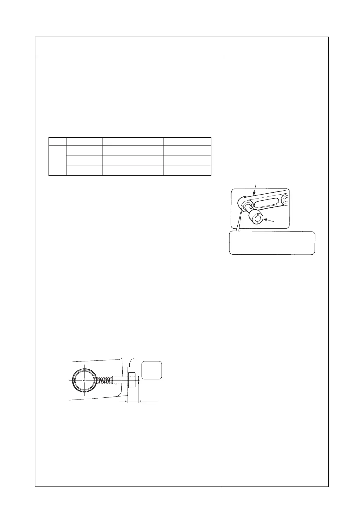
2. For coupling connecting shaft 5, insert needle rocking link !1 between
connecting shaft 5 and connecting shaft collar 6, and tighten
setscrew !5 in the connecting shaft collar so that there is no play.
13) Adjusting needle rocking "0" position
1. Set the mode to the hook adjusting mode (refer to (12) Adjusting the
needle-to-hook timing and the needle guard) of 3. STANDARD
ADJUSTMENT.), determine needle entry "0", and tighten setscrew
8 in the needle bar support base bracket.
14) Checking the lateral torque of the needle bar support base
Check that the torque of pulling and pushing is less than 10N within
the range of 10 mm of the needle bar rocking.
Measure at A and B sections using the spring balancer as shown in
the figure.
15) Tightening the slide resistance screw
1. Adjust the height of the slide resistance screw so that it becomes the
height of the spring measured in advance (factory-adjusted value) at
5) Releasing the slide resistance screw or the aimed value of pulling
and pushing is 14N to 15N (11N to 18N in the whole region) within
the range of 10 mm of the needle bar rocking at A and B sections
using the spring balancer as shown in the figure.
In addition, the height of the screw can be adjusted to 5.5 ± 1 mm
16) Assembling the outer components
1. Assemble the outer cover removed.
17) Adjusting the hook and the height of the needle bar
1. Perform adjusting of the height of the needle bar, and needle-to-blade
point of the hook in the hook adjusting mode (refer to (12) Adjusting
the needle-to-hook timing and the needle guard of 3. STANDARD
ADJUSTMENT) using timing gauge E.
™ When centering is not obtained,
needle bar support base bracket 7
moves, and the lateral needle
rocking torque becomes heavy
when tightening screw 8 in the
needle bar support base bracket in
the next process, resulting in step-
out.
™ When tightening setscrews 4 in the
needle bar support base shaft
bracket collar, be careful so as not
to damage sensor slit 9 or origin
sensor !0.
™ When the torque becomes more
than 10N within the range of 10 mm
of needle bar rocking, perform re-
adjustment from step 12).
™ When the machine is operated with
the abnormal torque, worn-out or
step-out will be caused.
™ When the adjustment is performed
with the value other than the
specified value, problems such as
step-out, deterioration of sewing
performance, worn-out, etc. can be
considered. Be sure to use the
machine with the specified value.
No. Part No. Name of part Shaft diameter
40008119 Connecting shaft A Large
40008120 Connecting shaft B Medium
40008118 Connecting shaft C Small
Dimension of height of
screw
5.5 ±
1 mm
Apply exclusive grease to the
grooves of the holes in connecting
shaft 5 and needle rocking link !1.
5
!1
5
 Loading...