Do you have a question about the JUKI LBH-1790 Series and is the answer not in the manual?
Ensures correct timing between needle and hook for stitches.
Sets correct tension for the feed timing belt.
Ensures the cutting knife drops into the throat plate groove.
Sets the cutting knife's movement and starting position.
Fine-tuning the needle thread trimming mechanism.
Adjusting the bobbin thread trimming mechanism.
Lists default parameter values for different sewing shapes.
Troubleshooting common sewing issues and their causes.
Troubleshooting mechanical problems and their solutions.
Troubleshooting electrical issues and their causes.
Detailed power circuit for 3-phase 200-240V.
Detailed power circuit for single-phase 220-240V.
Detailed power circuit for single-phase 100V.
Circuit diagram for the AC servo motor.
Circuit diagram for stepping motors and solenoids.
Shows connections between control box and machine head.
| Brand | JUKI |
|---|---|
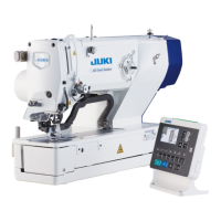
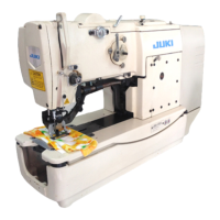
| Model | LBH-1790 Series |
| Category | Sewing Machine |
| Language | English |